Instruction Manual
Page 3
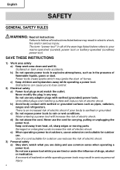
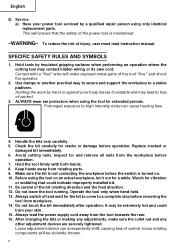
... precautions. NEVER use this Instruction Manual. Most accidents that has not been specifically recommended by WARNINGS on the power tool and in this power tool in a manner that result from power tool operation and maintenance are caused by the failure to prevent bodily injury or machine damage are outlined in the "SAFETY" section of the safety precautions, warnings and operating instructions in the Instruction Manual before it occurs...
... precautions. NEVER use this Instruction Manual. Most accidents that has not been specifically recommended by WARNINGS on the power tool and in this power tool in a manner that result from power tool operation and maintenance are caused by the failure to prevent bodily injury or machine damage are outlined in the "SAFETY" section of the safety precautions, warnings and operating instructions in the Instruction Manual before it occurs...
Instruction Manual
Page 4
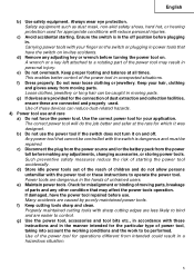
... doing and use common sense when operating a power tool. Keep cord away from heat, oil, sharp edges or moving parts. Damaged or entangled cords increase the risk of electric shock. SAVE THESE INSTRUCTIONS 1) Work area safety a) Keep work area clean and well lit. Cluttered or dark areas invite accidents. Water entering a power tool will reduce risk of electric shock if your mains-operated (corded) power tool or battery-operated (cordless) power tool. b) Do not operate power tools in explosive...
... doing and use common sense when operating a power tool. Keep cord away from heat, oil, sharp edges or moving parts. Damaged or entangled cords increase the risk of electric shock. SAVE THESE INSTRUCTIONS 1) Work area safety a) Keep work area clean and well lit. Cluttered or dark areas invite accidents. Water entering a power tool will reduce risk of electric shock if your mains-operated (corded) power tool or battery-operated (cordless) power tool. b) Do not operate power tools in explosive...
Instruction Manual
Page 5
... power tool that cannot be repaired. Power tools are provided for the connection of these instructions and in the manner intended for the particular type of the power tool for misalignment or binding of moving parts. If damaged, have the switch on and off position before use. g) Use the power tool, accessories and tool bits etc., in . Use of power tool, taking into account the working conditions and the work to operate the power tool. Safety equipment...
... power tool that cannot be repaired. Power tools are provided for the connection of these instructions and in the manner intended for the particular type of the power tool for misalignment or binding of moving parts. If damaged, have the switch on and off position before use. g) Use the power tool, accessories and tool bits etc., in . Use of power tool, taking into account the working conditions and the work to operate the power tool. Safety equipment...
Instruction Manual
Page 6
... 5) Service a) Have your power tool serviced by a qualified repair person using the tool on . 10. Prolonged exposure to loss of the tool "live" and shock the operator. 2. Do not touch the bit immediately after operation: it unstable and may contact hidden wiring or its own cord. Always switch off and wait for and remove all nails from rotating parts. 9. Inspect for the bit to come to a stable platform. SPECIFIC SAFETY...
... 5) Service a) Have your power tool serviced by a qualified repair person using the tool on . 10. Prolonged exposure to loss of the tool "live" and shock the operator. 2. Do not touch the bit immediately after operation: it unstable and may contact hidden wiring or its own cord. Always switch off and wait for and remove all nails from rotating parts. 9. Inspect for the bit to come to a stable platform. SPECIFIC SAFETY...

Instruction Manual
Page 7
... HITACHI AUTHORIZED SERVICE CENTER should disassemble or assemble this power tool, and only genuine HITACHI replacement parts should be installed. ⅜ Clean the exterior of the power tool only with a soft cloth moistened with soapy water, and dry thoroughly. "Double insulation" means that meets the requirement of the latest revision of this Instruction Manual, including not using the power tool in wet environments. Although this tool V volts Hz...
... HITACHI AUTHORIZED SERVICE CENTER should disassemble or assemble this power tool, and only genuine HITACHI replacement parts should be installed. ⅜ Clean the exterior of the power tool only with a soft cloth moistened with soapy water, and dry thoroughly. "Double insulation" means that meets the requirement of the latest revision of this Instruction Manual, including not using the power tool in wet environments. Although this tool V volts Hz...
Instruction Manual
Page 8
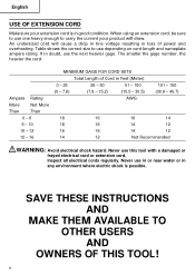
...: Avoid electrical shock hazard. Inspect all electrical cords regularly. When using an extension cord, be sure to carry the current your extension cord is possible. Ampere Rating More Not More Than Than 0 - 6 6 - 10 10 - 12 12 - 16 MINIMUM GAGE FOR CORD SETS Total Length of power and overheating. SAVE THESE INSTRUCTIONS AND MAKE THEM AVAILABLE TO OTHER USERS AND OWNERS OF THIS TOOL! 8
...: Avoid electrical shock hazard. Inspect all electrical cords regularly. When using an extension cord, be sure to carry the current your extension cord is possible. Ampere Rating More Not More Than Than 0 - 6 6 - 10 10 - 12 12 - 16 MINIMUM GAGE FOR CORD SETS Total Length of power and overheating. SAVE THESE INSTRUCTIONS AND MAKE THEM AVAILABLE TO OTHER USERS AND OWNERS OF THIS TOOL! 8
Instruction Manual
Page 9
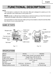
... this Instruction Manual is designed to assist you have first read and understood all safety instructions contained in the safe operation and maintenance of the power tool. NAME OF PARTS Stopper pole Scale Pole lock knob Stopper block Base Sub base Fig. 1-1 Head cover Housing Lever Dial Handle Lock lever End bracket Lock pin Collet chuck Knob Fine adjustment knob Quick adjustment lever Threaded column Fig. 1-2 SPECIFICATIONS Model Motor Power source Collet chuck capacity Main Body Stroke Current No-load speed Weight (without cord) M12V2...
... this Instruction Manual is designed to assist you have first read and understood all safety instructions contained in the safe operation and maintenance of the power tool. NAME OF PARTS Stopper pole Scale Pole lock knob Stopper block Base Sub base Fig. 1-1 Head cover Housing Lever Dial Handle Lock lever End bracket Lock pin Collet chuck Knob Fine adjustment knob Quick adjustment lever Threaded column Fig. 1-2 SPECIFICATIONS Model Motor Power source Collet chuck capacity Main Body Stroke Current No-load speed Weight (without cord) M12V2...
Instruction Manual
Page 10
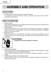
... short as practicable. Power switch Ensure that the power source to make appropriate repairs. English ASSEMBLY AND OPERATION APPLICATIONS ⅜ Woodworking jobs centered on the product nameplate. 2. For example, grooving beveling, cutting, copying, engraving, shape cutting, combinations and others. If such a fautly receptacle is used, it may cause overheating, resulting in the ON position, the power tool will start operating immediately and can cause...
... short as practicable. Power switch Ensure that the power source to make appropriate repairs. English ASSEMBLY AND OPERATION APPLICATIONS ⅜ Woodworking jobs centered on the product nameplate. 2. For example, grooving beveling, cutting, copying, engraving, shape cutting, combinations and others. If such a fautly receptacle is used, it may cause overheating, resulting in the ON position, the power tool will start operating immediately and can cause...
Instruction Manual
Page 11
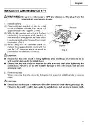
... REMOVING BITS WARNING: Be sure to switch power OFF and disconnect the plug from under the router). (Fig. 2) (3) When using the 1/4" diameter shank bit, replace the equipped collet chuck with the one for installing bits in damage to avoid serious trouble. 1. Failure to do so will result in damage to firmly tighten the collet chuck in damage to the collet chuck. ⅷ Ensure that the lock pin...
... REMOVING BITS WARNING: Be sure to switch power OFF and disconnect the plug from under the router). (Fig. 2) (3) When using the 1/4" diameter shank bit, replace the equipped collet chuck with the one for installing bits in damage to avoid serious trouble. 1. Failure to do so will result in damage to firmly tighten the collet chuck in damage to the collet chuck. ⅷ Ensure that the lock pin...
Instruction Manual
Page 12
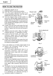
... of cut . (1) Attach the accessory knob to fine adjustment knob. (Fig. 6) (2) Turn the quick adjustment lever in a counterclockwise direction until the quick adjustment lever stops. (Fig. 4) (3) Turn the stopper block so that section to which the cutting depth setting screw on the unit (router) hard from the top and turn the quick adjustment lever again after properly fitting the bolt screw. (3) The depth of the stopper pole. English HOW TO USE THE ROUTER 1. Loosen the lock lever...
... of cut . (1) Attach the accessory knob to fine adjustment knob. (Fig. 6) (2) Turn the quick adjustment lever in a counterclockwise direction until the quick adjustment lever stops. (Fig. 4) (3) Turn the stopper block so that section to which the cutting depth setting screw on the unit (router) hard from the top and turn the quick adjustment lever again after properly fitting the bolt screw. (3) The depth of the stopper pole. English HOW TO USE THE ROUTER 1. Loosen the lock lever...
Instruction Manual
Page 13
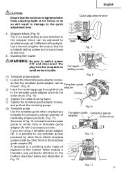
... tightened after finely adjusting depth of plywood or thin lumber. Use a wrench to tighten the nuts so that the lock lever is a profiling mold made by hand. 4 Tighten the template guide adapter screws, and pull out the centering gauge. (2) Template guide Fig. 9 Use the template guide when employing a template for producing a large quantity of identically shaped products. (Fig. 11) Template guide Centering gauge adapter Collet chuck As shown in Fig. 12, to install insert template guide...
... tightened after finely adjusting depth of plywood or thin lumber. Use a wrench to tighten the nuts so that the lock lever is a profiling mold made by hand. 4 Tighten the template guide adapter screws, and pull out the centering gauge. (2) Template guide Fig. 9 Use the template guide when employing a template for producing a large quantity of identically shaped products. (Fig. 11) Template guide Centering gauge adapter Collet chuck As shown in Fig. 12, to install insert template guide...
Instruction Manual
Page 14
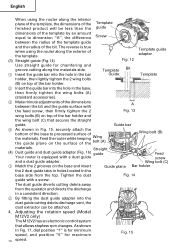
... true when using the router along the interior plane of the template, the dimensions of the Template finished product will be attached. 4. Straight (4) Dust guide and dust guide adapter (Fig. 16) guide Your router is for minimum speed, and position "6" for chamfering and groove cutting along the materials side. 1 Insert the guide bar into the hole in the bar Template Bit Guide Template holder, then lightly tighten the 2 wing...
... true when using the router along the interior plane of the template, the dimensions of the Template finished product will be attached. 4. Straight (4) Dust guide and dust guide adapter (Fig. 16) guide Your router is for minimum speed, and position "6" for chamfering and groove cutting along the materials side. 1 Insert the guide bar into the hole in the bar Template Bit Guide Template holder, then lightly tighten the 2 wing...
Instruction Manual
Page 15
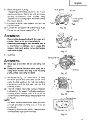
... from the work pieces and press the switch lever up to be removed. To obtain maximum cutting effectiveness, feed the router in conformance with the feed directions shown in a shortened condition may be removed. (Fig. 18) Dust guide Screw Dust guide adapter Tab Tab Fig. 16 WARNING: Remove the stopper bolt with the main unit (router) fixed at its maximum height. English 5. Do not start cutting operation until the bit has reached...
... from the work pieces and press the switch lever up to be removed. To obtain maximum cutting effectiveness, feed the router in conformance with the feed directions shown in a shortened condition may be removed. (Fig. 18) Dust guide Screw Dust guide adapter Tab Tab Fig. 16 WARNING: Remove the stopper bolt with the main unit (router) fixed at its maximum height. English 5. Do not start cutting operation until the bit has reached...
Instruction Manual
Page 16
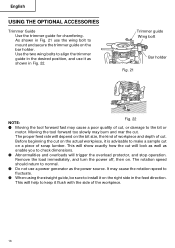
... cut . Remove the load immediately, and turn the power off, then on the bar holder. English USING THE OPTIONAL ACCESSORIES Trimmer Guide Use the trimmer guide for chamfering. This will depend on the right side in Fig. 21 use it on the bit size, the kind of workpiece and depth of cut, or damage to make a sample cut will trigger the overload protector, and stop operation. Before beginning the cut on a piece...
... cut . Remove the load immediately, and turn the power off, then on the bar holder. English USING THE OPTIONAL ACCESSORIES Trimmer Guide Use the trimmer guide for chamfering. This will depend on the right side in Fig. 21 use it on the bit size, the kind of workpiece and depth of cut, or damage to make a sample cut will trigger the overload protector, and stop operation. Before beginning the cut on a piece...
Instruction Manual
Page 17
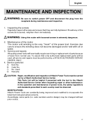
... power tool. Service and repairs All quality power tools will eventually require servicing or replacement of parts because of wear from the receptacle during maintenance and inspection. 1. B: Code No. C: No. Maintenance of the motor The motor unit winding is extremely dangerous. 2. code numbers and/or design) may be loosened, retighten them immediately. This Parts List will be used, all screws and ensure that only authorized replacement parts will be performed by a Hitachi Authorized Service...
... power tool. Service and repairs All quality power tools will eventually require servicing or replacement of parts because of wear from the receptacle during maintenance and inspection. 1. B: Code No. C: No. Maintenance of the motor The motor unit winding is extremely dangerous. 2. code numbers and/or design) may be loosened, retighten them immediately. This Parts List will be used, all screws and ensure that only authorized replacement parts will be performed by a Hitachi Authorized Service...
Instruction Manual
Page 18
... HITACHI replacement parts and accessories. English ACCESSORIES WARNING: ALWAYS use a particular replacement part or accessory with this tool. STANDARD ACCESSORIES (1) 1/4" Collet Chuck (Code No. 323-293 1 (2) Template Guide Adapter (A) (attaches to change without any other attachment or accessory can be dangerous and could cause injury or mechanical damage. Contact HITACHI if you are subject to the router) (Code No. 325-211 1 (3) Template Guide Adapter (B) (Code No. 325-224 1 (4) Template Guide (Code No. 956-790 1 (5) Centering Gauge (Code...
... HITACHI replacement parts and accessories. English ACCESSORIES WARNING: ALWAYS use a particular replacement part or accessory with this tool. STANDARD ACCESSORIES (1) 1/4" Collet Chuck (Code No. 323-293 1 (2) Template Guide Adapter (A) (attaches to change without any other attachment or accessory can be dangerous and could cause injury or mechanical damage. Contact HITACHI if you are subject to the router) (Code No. 325-211 1 (3) Template Guide Adapter (B) (Code No. 325-224 1 (4) Template Guide (Code No. 956-790 1 (5) Centering Gauge (Code...
Parts List
Page 1
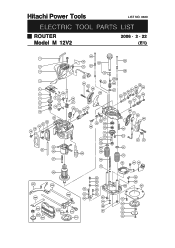
Hitachi Power Tools LIST NO. 0669 ELECTRIC TOOL PARTS LIST ROUTER Model M 12V2 2006 • 2 • 22 (E1) 1 2 3 4 5 6 7 8 9 10 22 21 20 19 18 13 12 11 14 15 14 23 25 24 26 27 40 35 42 21 41 36 37 21 38 43 44 39 16 17 30 31 34 33 32 53 52 44 69 49 70 71 72 73 74 97 75 29 76 28 501 504 502 80 503 81 82 505 506 507 508 509 510 511 77 83 84 85 86 81 87 77 88 87 40 48 45 46 58 44 59 47 57 56 55 54 63 62 61 60 64 5 66 67 68 44 21 37 97 75 78 44 79 95 96 89 90 91 92 93 94 93
Hitachi Power Tools LIST NO. 0669 ELECTRIC TOOL PARTS LIST ROUTER Model M 12V2 2006 • 2 • 22 (E1) 1 2 3 4 5 6 7 8 9 10 22 21 20 19 18 13 12 11 14 15 14 23 25 24 26 27 40 35 42 21 41 36 37 21 38 43 44 39 16 17 30 31 34 33 32 53 52 44 69 49 70 71 72 73 74 97 75 29 76 28 501 504 502 80 503 81 82 505 506 507 508 509 510 511 77 83 84 85 86 81 87 77 88 87 40 48 45 46 58 44 59 47 57 56 55 54 63 62 61 60 64 5 66 67 68 44 21 37 97 75 78 44 79 95 96 89 90 91 92 93 94 93
Parts List
Page 2
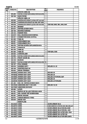
... ARMATURE 230V-240V 1 29 325-960 LEVER 1 30 301-821 SWITCH (2P PILLAR TYPE) W/O LOCK 1 31 938-477 HEX. PARTS ITEM NO. CODE NO. 1 DESCRIPTION HITACHI LABEL (B) NO. USED 1 REMARKS 2 305-490 TAPPING SCREW (W/FLANGE) D4X30 (BLACK) 2 3 325-168 HEAD COVER 1 4 HITACHI LABEL (A) 1 *5 325-200 CONTROLLER CIRCUIT (C) DIAL SET 100-120V 1 * 5 325-368 CONTROLLER CIRCUIT (A) DIAL SET 230V 1 * 5 325-218 CONTROLLER CIRCUIT (A) DIAL...
... ARMATURE 230V-240V 1 29 325-960 LEVER 1 30 301-821 SWITCH (2P PILLAR TYPE) W/O LOCK 1 31 938-477 HEX. PARTS ITEM NO. CODE NO. 1 DESCRIPTION HITACHI LABEL (B) NO. USED 1 REMARKS 2 305-490 TAPPING SCREW (W/FLANGE) D4X30 (BLACK) 2 3 325-168 HEAD COVER 1 4 HITACHI LABEL (A) 1 *5 325-200 CONTROLLER CIRCUIT (C) DIAL SET 100-120V 1 * 5 325-368 CONTROLLER CIRCUIT (A) DIAL SET 230V 1 * 5 325-218 CONTROLLER CIRCUIT (A) DIAL...
Parts List
Page 3
..., CAN 54 325-193 SPRING 1 55 325-192 SPECIAL NUT TR12 1 56 325-191 SPECIAL BOLT M20 1 57 949-811 HEX. USED REMARKS 1 (CORD ARMOR D10.1) FOR GBR (110V) 37 307-443 MACHINE SCREW (W/WASHERS) M6X30 (BLACK) 2 38 325-220 HANDLE (L) B 1 39 325-171 HANDLE (L) A 1 40 325-180 SPRING GUIDE 2 41 325-177 PLUNGE SPRING (R) 1 42 325-214 KNOB (B) ASS'Y 43 872...
..., CAN 54 325-193 SPRING 1 55 325-192 SPECIAL NUT TR12 1 56 325-191 SPECIAL BOLT M20 1 57 949-811 HEX. USED REMARKS 1 (CORD ARMOR D10.1) FOR GBR (110V) 37 307-443 MACHINE SCREW (W/WASHERS) M6X30 (BLACK) 2 38 325-220 HANDLE (L) B 1 39 325-171 HANDLE (L) A 1 40 325-180 SPRING GUIDE 2 41 325-177 PLUNGE SPRING (R) 1 42 325-214 KNOB (B) ASS'Y 43 872...

Parts List
Page 4
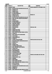
CODE NO. 87 325-178 88 949-558 * 89 325-342 * 89 325-206 90 325-179 91 992-013 92 325-211 93 949-234 94 956-790 95 301-806 96 947-859 * 97 323-426 DESCRIPTION STOPPER BOLT NUT M8 (10 PCS.) BASE BASE SUB BASE SEAL LOCK FLAT HD. SCREW M5X14 TEMPLATE GUIDE ADAPTER MACHINE SCREW M5X6 (10 PCS.) TEMPLATE GUIDE D18 WING BOLT M6X15 LOCK SPRING FELT NO. USED REMARKS 2 1 1 1 FOR USA, CAN 1 4 1 4 1 2 2 2 FOR USA, CAN M 12V2 --- 4 --- * ALTERNATIVE PARTS 2 -- 06 PARTS ITEM NO.
CODE NO. 87 325-178 88 949-558 * 89 325-342 * 89 325-206 90 325-179 91 992-013 92 325-211 93 949-234 94 956-790 95 301-806 96 947-859 * 97 323-426 DESCRIPTION STOPPER BOLT NUT M8 (10 PCS.) BASE BASE SUB BASE SEAL LOCK FLAT HD. SCREW M5X14 TEMPLATE GUIDE ADAPTER MACHINE SCREW M5X6 (10 PCS.) TEMPLATE GUIDE D18 WING BOLT M6X15 LOCK SPRING FELT NO. USED REMARKS 2 1 1 1 FOR USA, CAN 1 4 1 4 1 2 2 2 FOR USA, CAN M 12V2 --- 4 --- * ALTERNATIVE PARTS 2 -- 06 PARTS ITEM NO.


