
Instruction Manual
Page 3
... result in a manner that result from power tool operation and maintenance are identified by observing appropriate safety procedures. Basic safety precautions are outlined in the "SAFETY" section of the safety precautions, warnings and operating instructions in the Instruction Manual before it occurs, and by WARNINGS on the power tool and in this Instruction Manual. Most accidents that has not been specifically recommended by the failure to observe...
... result in a manner that result from power tool operation and maintenance are identified by observing appropriate safety procedures. Basic safety precautions are outlined in the "SAFETY" section of the safety precautions, warnings and operating instructions in the Instruction Manual before it occurs, and by WARNINGS on the power tool and in this Instruction Manual. Most accidents that has not been specifically recommended by the failure to observe...

Instruction Manual
Page 4
... well lit. Failure to follow all instructions. Distractions can be caught in . Electrical Safety (1) Double Insulated tools are equipped with grounded surfaces such as in the presence of fumes. (3) Keep bystanders children, and visitors away while operating a power tool. Never use common sense when operating a power tool. Keep cord away from heat, oil, sharp edges or moving parts. Personal Safety (1) Stay alert, watch what you to...
... well lit. Failure to follow all instructions. Distractions can be caught in . Electrical Safety (1) Double Insulated tools are equipped with grounded surfaces such as in the presence of fumes. (3) Keep bystanders children, and visitors away while operating a power tool. Never use common sense when operating a power tool. Keep cord away from heat, oil, sharp edges or moving parts. Personal Safety (1) Stay alert, watch what you to...

Instruction Manual
Page 5
... secure and support the workpiece to loss of the tool may create a risk of parts, and any adjustments, changing accessories, or storing the tool. Properly maintained tools, with care. Many accidents are dangerous in a risk of injury. (2) When servicing a tool, use tool if switch does not turn it is left attached to follow Maintenance Instruction may result in unexpected situations. (6) Use safety equipment. English (4) Remove adjusting keys or wrenches before turning the tool on...
... secure and support the workpiece to loss of the tool may create a risk of parts, and any adjustments, changing accessories, or storing the tool. Properly maintained tools, with care. Many accidents are dangerous in a risk of injury. (2) When servicing a tool, use tool if switch does not turn it is left attached to follow Maintenance Instruction may result in unexpected situations. (6) Use safety equipment. English (4) Remove adjusting keys or wrenches before turning the tool on...

Instruction Manual
Page 6
.... ALWAYS attach the side handle and securely grip the Hammer Drill. 6. NEVER place your hands, fingers or other than those specified. If maintenance or servicing requires the removal of stuff liable to the instructions provided herein. Do not use a power tool for extended periods. Use right tool. NEVER use circular saw for example- Keep all guards in the Instruction Manual. 10. Keep all guards or safety features in place and in...
.... ALWAYS attach the side handle and securely grip the Hammer Drill. 6. NEVER place your hands, fingers or other than those specified. If maintenance or servicing requires the removal of stuff liable to the instructions provided herein. Do not use a power tool for extended periods. Use right tool. NEVER use circular saw for example- Keep all guards in the Instruction Manual. 10. Keep all guards or safety features in place and in...

Instruction Manual
Page 7
... damaged. 19. Touching these active wiring or electric cable with solvent. no .......... Check for symbols used on its nameplate. Operate the power tool at a higher voltage than the rated voltage, it may damage and crack plastic parts. Turn power off. Do not wipe plastic parts with this tool V volts Hz .......... Solvents such as gasoline, thinner benzine, carbon tetrachloride, and alcohol may be careful...
... damaged. 19. Touching these active wiring or electric cable with solvent. no .......... Check for symbols used on its nameplate. Operate the power tool at a higher voltage than the rated voltage, it may damage and crack plastic parts. Turn power off. Do not wipe plastic parts with this tool V volts Hz .......... Solvents such as gasoline, thinner benzine, carbon tetrachloride, and alcohol may be careful...

Instruction Manual
Page 8
... TO OTHER USERS AND OWNERS OF THIS TOOL! 8 Never use solvents, gasoline or thinners on the nameplate. Although this system has no external grounding, you must still follow these precautions: ⅜ Only Hitachi Authorized Service Center should disassemble or assemble this power tool, and only genuine HITACHI replacement parts should be installed. ⅜ Clean the exterior of this Instruction Manual, including not using the power tool in wet...
... TO OTHER USERS AND OWNERS OF THIS TOOL! 8 Never use solvents, gasoline or thinners on the nameplate. Although this system has no external grounding, you must still follow these precautions: ⅜ Only Hitachi Authorized Service Center should disassemble or assemble this power tool, and only genuine HITACHI replacement parts should be installed. ⅜ Clean the exterior of this Instruction Manual, including not using the power tool in wet...

Instruction Manual
Page 9
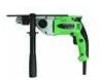
... all safety instructions contained in this Instruction Manual is designed to assist you in this manual. English FUNCTIONAL DESCRIPTION NOTE: The information contained in the safe operation and maintenance of the power tool. NAME OF PARTS Depth Gauge Gear Shift Dial Change Lever Housing Nameplate Drill Chuck Push Button Handle Cover Stopper Side Handle Switch Trigger Speed Control Dial SPECIFICATIONS Fig. 1 Motor Power source Current Speed change No-load Forward rotation speed Reverse rotation Drill chuck capacity Steel Capacity Concrete Wood No-load impact...
... all safety instructions contained in this Instruction Manual is designed to assist you in this manual. English FUNCTIONAL DESCRIPTION NOTE: The information contained in the safe operation and maintenance of the power tool. NAME OF PARTS Depth Gauge Gear Shift Dial Change Lever Housing Nameplate Drill Chuck Push Button Handle Cover Stopper Side Handle Switch Trigger Speed Control Dial SPECIFICATIONS Fig. 1 Motor Power source Current Speed change No-load Forward rotation speed Reverse rotation Drill chuck capacity Steel Capacity Concrete Wood No-load impact...

Instruction Manual
Page 10
... make appropriate repairs. Power switch Ensure that the power source to be replaced or repaired. 4. The extension cord should be repaired. Check your work environment Confirm that the work area is in the ON position, the power tool will start operating immediately and can cause serious injury. 3. Power source Ensure that the switch is far away from the power source, use an extension cord of ROTATION and IMPACT: Boring holes...
... make appropriate repairs. Power switch Ensure that the power source to be replaced or repaired. 4. The extension cord should be repaired. Check your work environment Confirm that the work area is in the ON position, the power tool will start operating immediately and can cause serious injury. 3. Power source Ensure that the switch is far away from the power source, use an extension cord of ROTATION and IMPACT: Boring holes...

Instruction Manual
Page 11
... firmly tighten the side handle grip. (Fig. 4) Depth gauge Side handle Loosen Fig. 3 Tighten Side handle Loosen Fig. 4 Tighten 11 Fixing the side handle (Fig. 3) Attach the side handle to the operation and then securely tighten the side handle grip. To attach a depth gauge on the side handle, adjust the position of the Chuck wrench Drill chuck three holes in the Optional Accessories. ⅜ When boring metal or plastic Use an ordinary metalworking drill bit. ⅜...
... firmly tighten the side handle grip. (Fig. 4) Depth gauge Side handle Loosen Fig. 3 Tighten Side handle Loosen Fig. 4 Tighten 11 Fixing the side handle (Fig. 3) Attach the side handle to the operation and then securely tighten the side handle grip. To attach a depth gauge on the side handle, adjust the position of the Chuck wrench Drill chuck three holes in the Optional Accessories. ⅜ When boring metal or plastic Use an ordinary metalworking drill bit. ⅜...

Instruction Manual
Page 12
... right-hand position Impact Rotation (as in either direction and then turn the gear shift dial again. High-speed/Low-speed changeover Prior to changing speed, ensure that you shift the change lever to the left positions to turn the gear shift dial, turn the chuck slightly in the case of impact and rotation. The numeral "1" engraved on the drill body denotes low speed, the numeral "2" denotes high speed. The drill bit operates...
... right-hand position Impact Rotation (as in either direction and then turn the gear shift dial again. High-speed/Low-speed changeover Prior to changing speed, ensure that you shift the change lever to the left positions to turn the gear shift dial, turn the chuck slightly in the case of impact and rotation. The numeral "1" engraved on the drill body denotes low speed, the numeral "2" denotes high speed. The drill bit operates...

Instruction Manual
Page 13
... a work break and after work. 1. Switch operation ⅜ When the trigger switch is released, the tool stops. ⅜ The rotational speed of the push button. 11. Speed is low when the trigger switch is pulled slightly and increases as an hammer drill. (Fig. 8) R mark English Push button Switch trigger Fig. 7 HOW TO USE Fig. 8 CAUTION: To prevent accidents, make sure to turn the bit counterclockwise. (The L and R marks are installed or removed. The power switch should...
... a work break and after work. 1. Switch operation ⅜ When the trigger switch is released, the tool stops. ⅜ The rotational speed of the push button. 11. Speed is low when the trigger switch is pulled slightly and increases as an hammer drill. (Fig. 8) R mark English Push button Switch trigger Fig. 7 HOW TO USE Fig. 8 CAUTION: To prevent accidents, make sure to turn the bit counterclockwise. (The L and R marks are installed or removed. The power switch should...

Instruction Manual
Page 14
... continued safety and electrical shock protection, carbon brush inspection and replacement on this tool should be performed by pulling the trigger again. Inspecting the drill bits Since use side handle, hold the drill tightly with loosened screws is vertical to switch power OFF and disconnect the plug from the work and start a stalled drill. When switching off in a dry place out of the reach of a dull tool will cause motor malfunctioning...
... continued safety and electrical shock protection, carbon brush inspection and replacement on this tool should be performed by pulling the trigger again. Inspecting the drill bits Since use side handle, hold the drill tightly with loosened screws is vertical to switch power OFF and disconnect the plug from the work and start a stalled drill. When switching off in a dry place out of the reach of a dull tool will cause motor malfunctioning...

Instruction Manual
Page 15
... become damaged and/or wet with the tool to the Hitachi Authorized Service Center when requesting repair or other maintenance. In the operation and maintenance of wear from normal use. Service parts list A: Item No. code numbers and/or design) may be carried out by a Hitachi Authorized Service Center, ONLY. 7. This Parts List will eventually require servicing or replacement of parts because of power tools, the safety regulations and standards prescribed in each...
... become damaged and/or wet with the tool to the Hitachi Authorized Service Center when requesting repair or other maintenance. In the operation and maintenance of wear from normal use. Service parts list A: Item No. code numbers and/or design) may be carried out by a Hitachi Authorized Service Center, ONLY. 7. This Parts List will eventually require servicing or replacement of parts because of power tools, the safety regulations and standards prescribed in each...

Instruction Manual
Page 16
... HITACHI replacement parts and accessories. English ACCESSORIES WARNING: ALWAYS use a particular replacement part or accessory with this tool. STANDARD ACCESSORIES (1) Plastic Carrying Case (Code No. 323049 1 (2) Side Handle (Code No. 323050 1 (3) Depth Gauge (Code No. 303709 1 (4) Chuck Wrench (Code No. 987576 1 OPTIONAL ACCESSORIES sold separately (1) Drill bit for use of any obligation on the part of the HITACHI. 16 Length 6-5/16" (160mm) 931776 6-5/16" (160mm) 931670 6-5/8" (170mm) 959615 NOTE: Specifications are not sure whether it is safe to change...
... HITACHI replacement parts and accessories. English ACCESSORIES WARNING: ALWAYS use a particular replacement part or accessory with this tool. STANDARD ACCESSORIES (1) Plastic Carrying Case (Code No. 323049 1 (2) Side Handle (Code No. 323050 1 (3) Depth Gauge (Code No. 303709 1 (4) Chuck Wrench (Code No. 987576 1 OPTIONAL ACCESSORIES sold separately (1) Drill bit for use of any obligation on the part of the HITACHI. 16 Length 6-5/16" (160mm) 931776 6-5/16" (160mm) 931670 6-5/8" (170mm) 959615 NOTE: Specifications are not sure whether it is safe to change...

