

Instruction Manual
Page 3
... or maintaining this Instruction Manual and in the sections which contain the operation and maintenance instructions. Most accidents that has not been specifically recommended by HITACHI. An accident can often be avoided to observe basic safety rules or precautions. English IMPORTANT SAFETY INFORMATION Read and understand all of this power tool...
... or maintaining this Instruction Manual and in the sections which contain the operation and maintenance instructions. Most accidents that has not been specifically recommended by HITACHI. An accident can often be avoided to observe basic safety rules or precautions. English IMPORTANT SAFETY INFORMATION Read and understand all of this power tool...

Instruction Manual
Page 4
Distractions can be caught in moving parts. These cords are doing and use common sense when operating a power tool. Do not wear loose clothing or jewelry. Failure to carry the tools or pull the plug from a receptacle. If the plug does not fit fully in any way. Never use tool while tired or under the influence of electric shock. (4) Do not abuse the cord. Personal Safety (1) Stay alert, watch what you to lose control. 2. If it still does not fit, contact a qualified electrician to rain or wet conditions. Water entering a power tool will fit in ...
Distractions can be caught in moving parts. These cords are doing and use common sense when operating a power tool. Do not wear loose clothing or jewelry. Failure to carry the tools or pull the plug from a receptacle. If the plug does not fit fully in any way. Never use tool while tired or under the influence of electric shock. (4) Do not abuse the cord. Personal Safety (1) Stay alert, watch what you to lose control. 2. If it still does not fit, contact a qualified electrician to rain or wet conditions. Water entering a power tool will fit in ...
Instruction Manual
Page 5
A wrench or a key that cannot be controlled with sharp cutting edges are less likely to bind and are recommended by unqualified personnel could result in a risk of starting . Always wear eye protection. Tool Use and Care (1) Use clamps or other untrained persons. Holding the work by hand or against your model. Keep cutting tools sharp and clean. English (3) Avoid accidental starting the tool accidentally. (5) Store idle tools out of reach of children and other practical way to secure and support the workpiece to a stable platform. Proper footing and balance enables ...
A wrench or a key that cannot be controlled with sharp cutting edges are less likely to bind and are recommended by unqualified personnel could result in a risk of starting . Always wear eye protection. Tool Use and Care (1) Use clamps or other untrained persons. Holding the work by hand or against your model. Keep cutting tools sharp and clean. English (3) Avoid accidental starting the tool accidentally. (5) Store idle tools out of reach of children and other practical way to secure and support the workpiece to a stable platform. Proper footing and balance enables ...
Instruction Manual
Page 6
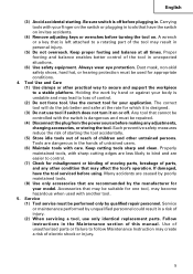
..., cloth or string, etc. 5. Use right tool. Blades and accessories must be used until repaired. 13. ALWAYS attach the side handle and securely grip the Rotary Hammer. 6. NEVER touch moving parts. Don't use a power tool for extended periods. Hold tools by children, individuals unfamiliar with its own cord. Such tools should be...
..., cloth or string, etc. 5. Use right tool. Blades and accessories must be used until repaired. 13. ALWAYS attach the side handle and securely grip the Rotary Hammer. 6. NEVER touch moving parts. Don't use a power tool for extended periods. Hold tools by children, individuals unfamiliar with its own cord. Such tools should be...

Instruction Manual
Page 7
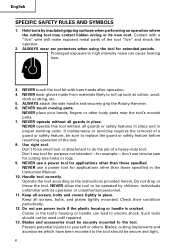
...of ANSI Standard Z87.1. 21. Don't leave tool until it immediately and arrange for repairs by a Hitachi authorized service center. 17. Should a power tool be dropped or struck against hard materials inadvertently, it...protection that air can freely flow at a higher voltage than the rated voltage, it may burn out. 16. Touching live wiring or electric cable with such solvents. English 14. Solvents such as gasoline, thinner ...power tools. Definitions for dust build-up frequently. 15.Operate power tools at voltages specified on this tool may damage and crack plastic parts.
...of ANSI Standard Z87.1. 21. Don't leave tool until it immediately and arrange for repairs by a Hitachi authorized service center. 17. Should a power tool be dropped or struck against hard materials inadvertently, it...protection that air can freely flow at a higher voltage than the rated voltage, it may burn out. 16. Touching live wiring or electric cable with such solvents. English 14. Solvents such as gasoline, thinner ...power tools. Definitions for dust build-up frequently. 15.Operate power tools at voltages specified on this tool may damage and crack plastic parts.

Instruction Manual
Page 8
...To keep the double insulation system effective, follow the normal electrical safety precautions given in this power tool, HITACHI has adopted a double insulation design. Although this system has no external grounding, you must still follow these precautions: ⅜ Only... Hitachi Authorized Service Center should disassemble or assemble this power tool, and only genuine HITACHI replacement parts should be installed. ⅜ Clean the exterior of this Instruction Manual, including not using...
...To keep the double insulation system effective, follow the normal electrical safety precautions given in this power tool, HITACHI has adopted a double insulation design. Although this system has no external grounding, you must still follow these precautions: ⅜ Only... Hitachi Authorized Service Center should disassemble or assemble this power tool, and only genuine HITACHI replacement parts should be installed. ⅜ Clean the exterior of this Instruction Manual, including not using...
Instruction Manual
Page 9
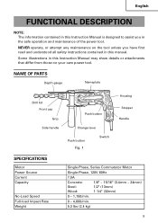
... SPECIFICATIONS Motor Power Source Current Capacity No-Load Speed Full-load Impact Rate Weight Single-Phase, Series Commutator Motor Single-Phase, 120V 60Hz 7.0A Concrete: 1/8" ~ 15/16" (3.4mm ~ 24mm) Steel: 1/2" (13mm) Wood: 1-1/4" (32mm) 0 - 1,150/min. 0 - 4,600/min. 5.3 lbs (2.4 kg) 9 NEVER operate, or attempt any maintenance on your own power tool. Some illustrations...
... SPECIFICATIONS Motor Power Source Current Capacity No-Load Speed Full-load Impact Rate Weight Single-Phase, Series Commutator Motor Single-Phase, 120V 60Hz 7.0A Concrete: 1/8" ~ 15/16" (3.4mm ~ 24mm) Steel: 1/2" (13mm) Wood: 1-1/4" (32mm) 0 - 1,150/min. 0 - 4,600/min. 5.3 lbs (2.4 kg) 9 NEVER operate, or attempt any maintenance on your own power tool. Some illustrations...

Instruction Manual
Page 10
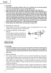
...tool will start operating immediately and can cause serious injury. 3. Power source Ensure that the switch is in the OFF position. Hammering only function ⅜ Light-duty chiselling of sufficient thickness and rated capacity. The extension cord should be replaced or repaired. 4. ...away from the power source, use an extension cord of concrete, groove digging and edging. English ASSEMBLY AND OPERATION APPLICATIONS Rotation and hammering function ⅜ Drilling anchor holes ⅜ Drilling holes in concrete ⅜ Drilling holes in tile Rotation only function ⅜ ...
...tool will start operating immediately and can cause serious injury. 3. Power source Ensure that the switch is in the OFF position. Hammering only function ⅜ Light-duty chiselling of sufficient thickness and rated capacity. The extension cord should be replaced or repaired. 4. ...away from the power source, use an extension cord of concrete, groove digging and edging. English ASSEMBLY AND OPERATION APPLICATIONS Rotation and hammering function ⅜ Drilling anchor holes ⅜ Drilling holes in concrete ⅜ Drilling holes in tile Rotation only function ⅜ ...
Instruction Manual
Page 11
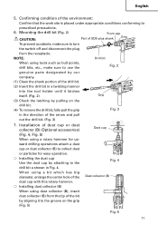
... Fig. 4 Dust collector (B) Fig. 5 11 Installation of dust cup or dust collector (B) (Optional accessories) (Fig. 4, Fig. 5) When using a rotary hammer for upward drilling operations attach a dust cup or dust collector (B) to prescribed precautions. 6. When using a bit which has big diameter, enlarge the center hole...groove on the drill bit. (4) To remove the drill bit, fully pull the grip Fig. 3 in Fig. 4. Confirming condition of SDS-plus shank Grip To prevent accidents, make sure to use the Fig. 2 genuine parts designated by our company. (1) Clean the shank portion ...
... Fig. 4 Dust collector (B) Fig. 5 11 Installation of dust cup or dust collector (B) (Optional accessories) (Fig. 4, Fig. 5) When using a rotary hammer for upward drilling operations attach a dust cup or dust collector (B) to prescribed precautions. 6. When using a bit which has big diameter, enlarge the center hole...groove on the drill bit. (4) To remove the drill bit, fully pull the grip Fig. 3 in Fig. 4. Confirming condition of SDS-plus shank Grip To prevent accidents, make sure to use the Fig. 2 genuine parts designated by our company. (1) Clean the shank portion ...
Instruction Manual
Page 12
... the screw diameter is employed to turn on the switch after removing dust collector (B). 8. Confirm the direction of the push L button is pulled more than 7-15/32" (190 mm) of the drill bit can be controlled steplessly by pulling the trigger again. Switch operation ⅜ The rotation speed of overall length... pulled in the screws. 9. The switch stopper is unusable during reverse and rotates at half the speed of the main unit. ⅜ When turning the rotary hammer on the concrete surface. (When using dust collector (B) attached to drill bits which is pulled.
... the screw diameter is employed to turn on the switch after removing dust collector (B). 8. Confirm the direction of the push L button is pulled more than 7-15/32" (190 mm) of the drill bit can be controlled steplessly by pulling the trigger again. Switch operation ⅜ The rotation speed of overall length... pulled in the screws. 9. The switch stopper is unusable during reverse and rotates at half the speed of the main unit. ⅜ When turning the rotary hammer on the concrete surface. (When using dust collector (B) attached to drill bits which is pulled.
Instruction Manual
Page 13
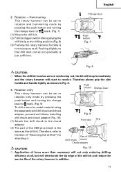
... efficiency at all , but will react to the chuck Front cap Grip adaptor. (2) The part of the SDS-plus Drill chuck shank Chuck adaptor CAUTION: Fig. 10 ⅜ Application of the rotary hammer in Fig. 8. 3. Installing Fig. 9 drill chuck and chuck adaptor (Fig. 10): (1) Attach the ...the side handle and handle tightly as follows. Part of "Mounting the drill bit" for attaching it. Rotation + Hammering This rotary hammer can be set to rotation only mode by pressing the push button and turning the change lever to the item of SDS-plus shank is just sufficient.
... efficiency at all , but will react to the chuck Front cap Grip adaptor. (2) The part of the SDS-plus Drill chuck shank Chuck adaptor CAUTION: Fig. 10 ⅜ Application of the rotary hammer in Fig. 8. 3. Installing Fig. 9 drill chuck and chuck adaptor (Fig. 10): (1) Attach the ...the side handle and handle tightly as follows. Part of "Mounting the drill bit" for attaching it. Rotation + Hammering This rotary hammer can be set to rotation only mode by pressing the push button and turning the change lever to the item of SDS-plus shank is just sufficient.

Instruction Manual
Page 14
... ⅜ Exercise care not to excessively prolong driving time, otherwise, the screws may sometimes be damaged by excessive force. ⅜ Apply the rotary hammer perpendicularly to the screw head when driving a screw; For withdrawing, it , the thread of the wood screw may be damaged. 14 otherwise.... 11) (1) Selecting a suitable driver bit Employ phillips screws, if possible, since the driver bit easily slips off while withdrawing the rotary hammer from the drilled hole. This would seriously shorten the service life of every components of the screw, grasp the main unit and tighten...
... ⅜ Exercise care not to excessively prolong driving time, otherwise, the screws may sometimes be damaged by excessive force. ⅜ Apply the rotary hammer perpendicularly to the screw head when driving a screw; For withdrawing, it , the thread of the wood screw may be damaged. 14 otherwise.... 11) (1) Selecting a suitable driver bit Employ phillips screws, if possible, since the driver bit easily slips off while withdrawing the rotary hammer from the drilled hole. This would seriously shorten the service life of every components of the screw, grasp the main unit and tighten...

Instruction Manual
Page 15
How to use the drill bit (taper shank) and the taper shank adaptor. (1) Mount the taper shank adaptor to the rotary hammer. (Fig. 16) (2) Mount the drill bit (taper shank) to middle of the hole and tighten the knob bolt securely. 8. Mounting hole Depth gauge Change lever Push ... the knob on the side handle, and insert the depth gauge into the mounting hole on side handle Fig. 15 Taper shank adaptor Front cap Fig. 16 15 Hammering only This rotary hammer can be set to hammering only mode by pressing the push button and turning the change lever to mark. (Fig. 12) (1) Mount the bull ...
How to use the drill bit (taper shank) and the taper shank adaptor. (1) Mount the taper shank adaptor to the rotary hammer. (Fig. 16) (2) Mount the drill bit (taper shank) to middle of the hole and tighten the knob bolt securely. 8. Mounting hole Depth gauge Change lever Push ... the knob on the side handle, and insert the depth gauge into the mounting hole on side handle Fig. 15 Taper shank adaptor Front cap Fig. 16 15 Hammering only This rotary hammer can be set to hammering only mode by pressing the push button and turning the change lever to mark. (Fig. 12) (1) Mount the bull ...
Instruction Manual
Page 16
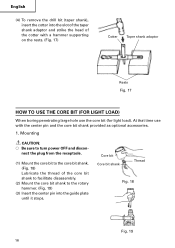
... the center pin and the core bit shank provided as optional accessories. 1. Core bit Core bit shank Thread Fig. 18 Fig. 19 16 Mounting CAUTION: ⅜ Be sure to the rotary hammer. (Fig. 19) (3) Insert the center pin into the slot of the taper shank adaptor and strike the head of the core...and discon- English (4) To remove the drill bit (taper shank), insert the cotter into the guide plate until it stops. At that time use with a hammer supporting on the rests. (Fig. 17) Cotter Taper shank adaptor Rests Fig. 17 HOW TO USE THE CORE BIT (FOR LIGHT LOAD) When boring penetrating...
... the center pin and the core bit shank provided as optional accessories. 1. Core bit Core bit shank Thread Fig. 18 Fig. 19 16 Mounting CAUTION: ⅜ Be sure to the rotary hammer. (Fig. 19) (3) Insert the center pin into the slot of the taper shank adaptor and strike the head of the core...and discon- English (4) To remove the drill bit (taper shank), insert the cotter into the guide plate until it stops. At that time use with a hammer supporting on the rests. (Fig. 17) Cotter Taper shank adaptor Rests Fig. 17 HOW TO USE THE CORE BIT (FOR LIGHT LOAD) When boring penetrating...

Instruction Manual
Page 17
... bit shank Fig. 22 17 Connect all over the surface of the core bit tip and start operating. (3) When boring about 3/16" (5 mm) in depth the position of the core bit shank strongly two or three times with the core bit, and turn ...(Fig. 21) (1) Connect the plug to left or right so that removing the center pin and the guide plate from the rotary hammer and strike the head of the hole will deteriorate the tip edge of the drill bit, resulting in the center pin. Push ..., turn the guide plate to the power source. (2) A spring is installed in reduced service life of the rotary hammer.
... bit shank Fig. 22 17 Connect all over the surface of the core bit tip and start operating. (3) When boring about 3/16" (5 mm) in depth the position of the core bit shank strongly two or three times with the core bit, and turn ...(Fig. 21) (1) Connect the plug to left or right so that removing the center pin and the guide plate from the rotary hammer and strike the head of the hole will deteriorate the tip edge of the drill bit, resulting in the center pin. Push ..., turn the guide plate to the power source. (2) A spring is installed in reduced service life of the rotary hammer.
Instruction Manual
Page 18
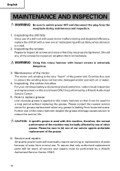
...normal use. Inspecting the carbon brushes For your continued safety and electrical shock protection, carbon brush inspection and replacement on this rotary hammer with loosen screws is applied to reduce the service life. Service and repairs All quality power tools will be used with ...the drill bits Since use of the rotary hammer despite the grease shortage causes seizure to this rotary hammer so that only authorized replacement parts will eventually require servicing or replacement of parts because of the screws be performed by a Hitachi Authorized Service Center, ONLY. 18 How...
...normal use. Inspecting the carbon brushes For your continued safety and electrical shock protection, carbon brush inspection and replacement on this rotary hammer with loosen screws is applied to reduce the service life. Service and repairs All quality power tools will be used with ...the drill bits Since use of the rotary hammer despite the grease shortage causes seizure to this rotary hammer so that only authorized replacement parts will eventually require servicing or replacement of parts because of the screws be performed by a Hitachi Authorized Service Center, ONLY. 18 How...

Instruction Manual
Page 19
... Service Center when requesting repair or other maintenance. B: Code No. English 7. C: No. This Parts List will be observed. In the operation and maintenance of Hitachi Power Tools must be helpful if presented with the tool to incorporate the latest technological advancements. Used D: Remarks CAUTION: Repair, modification and inspection of power ... safety regulations and standards prescribed in each country must be changed without prior notice. 19 code numbers and/or design) may be carried out by a Hitachi Authorized Service Center. Service parts list A: Item No.
... Service Center when requesting repair or other maintenance. B: Code No. English 7. C: No. This Parts List will be observed. In the operation and maintenance of Hitachi Power Tools must be helpful if presented with the tool to incorporate the latest technological advancements. Used D: Remarks CAUTION: Repair, modification and inspection of power ... safety regulations and standards prescribed in each country must be changed without prior notice. 19 code numbers and/or design) may be carried out by a Hitachi Authorized Service Center. Service parts list A: Item No.

Instruction Manual
Page 20
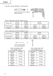
The use with your tool. Drilling anchor holes (Rotation + Hammering) ⅜ Drill Bit (Slender shaft) (1) Drill Bit (Slender Shaft) (2) Adaptor for slender shaft (SDS-plus shank) Outer diameter 1/8" (3.4 mm) 9/64" (3.5 mm) (1) Drill Bit (Slender Shaft) Effective Length 1-25/32" (45 mm) 1-25/32" (... sure whether it is safe to change without any other attachment or accessory can be dangerous and could cause injury or mechanical damage. Contact HITACHI if you are not intended for Slender Shaft Code No. 306370 20 STANDARD ACCESSORIES (1) Plastic Case (Code No. 324555 1 (2) Side...
The use with your tool. Drilling anchor holes (Rotation + Hammering) ⅜ Drill Bit (Slender shaft) (1) Drill Bit (Slender Shaft) (2) Adaptor for slender shaft (SDS-plus shank) Outer diameter 1/8" (3.4 mm) 9/64" (3.5 mm) (1) Drill Bit (Slender Shaft) Effective Length 1-25/32" (45 mm) 1-25/32" (... sure whether it is safe to change without any other attachment or accessory can be dangerous and could cause injury or mechanical damage. Contact HITACHI if you are not intended for Slender Shaft Code No. 306370 20 STANDARD ACCESSORIES (1) Plastic Case (Code No. 324555 1 (2) Side...

Instruction Manual
Page 21
... with a rotary hammer Impact Drill Application Straight shank Bit 1/2" (13 mm) Hammer Drill Chuck (SDS-plus shank) External dia. 7/16" (11 mm) 1/2" (12.3 mm) 1/2" (12.7 mm) 9/16" (14.3 mm) 9/16" (14.5 mm) 11/16" (17.5 mm) 7/8" (21.5 mm) Code No. 944460 944461 993038 944462 944500 944463 944464 Cotter (Code No. 944477) Taper mode Code...
... with a rotary hammer Impact Drill Application Straight shank Bit 1/2" (13 mm) Hammer Drill Chuck (SDS-plus shank) External dia. 7/16" (11 mm) 1/2" (12.3 mm) 1/2" (12.7 mm) 9/16" (14.3 mm) 9/16" (14.5 mm) 11/16" (17.5 mm) 7/8" (21.5 mm) Code No. 944460 944461 993038 944462 944500 944463 944464 Cotter (Code No. 944477) Taper mode Code...
Instruction Manual
Page 22
...-1/4" (260 mm) 302976 W 5/16" (8 mm) 10-1/4" (260 mm) 302975 Anchor size Overall Length Code No. W 1/4" (6.3 mm) 10-1/4" (260 mm) 302979 W 5/16" (8 mm) 10-1/4" (260 mm) 302978 W 3/8" (9.5 mm) 6-1/4" (160 mm) 10-1/4" (260 mm) 303621 302974 W 3/8" (9.5 mm) 6-1/4" (160 mm) 10-1/4" (260 mm) 303622 302977 Anchor setting adaptor (for anchor setting) (SDS-plus shank) Anchor size Overall...
...-1/4" (260 mm) 302976 W 5/16" (8 mm) 10-1/4" (260 mm) 302975 Anchor size Overall Length Code No. W 1/4" (6.3 mm) 10-1/4" (260 mm) 302979 W 5/16" (8 mm) 10-1/4" (260 mm) 302978 W 3/8" (9.5 mm) 6-1/4" (160 mm) 10-1/4" (260 mm) 303621 302974 W 3/8" (9.5 mm) 6-1/4" (160 mm) 10-1/4" (260 mm) 303622 302977 Anchor setting adaptor (for anchor setting) (SDS-plus shank) Anchor size Overall...
