
Instruction Manual
Page 3
.... NEVER use this power tool in death or serious injury. NOTE emphasizes essential information. 3 CAUTION indicates a potentially hazardous situations which contain the operation and maintenance instructions. Basic safety precautions are identified by HITACHI. Hazards that must be avoided by recognizing a potentially hazardous situation before operating or maintaining this Instruction Manual. English IMPORTANT SAFETY INFORMATION Read and understand all of this Instruction Manual and in...
.... NEVER use this power tool in death or serious injury. NOTE emphasizes essential information. 3 CAUTION indicates a potentially hazardous situations which contain the operation and maintenance instructions. Basic safety precautions are identified by HITACHI. Hazards that must be avoided by recognizing a potentially hazardous situation before operating or maintaining this Instruction Manual. English IMPORTANT SAFETY INFORMATION Read and understand all of this Instruction Manual and in...
Instruction Manual
Page 4
... use an outdoor extension cord marked "W-A" or "W". Be sure switch is wider than the other.) This plug will increase the risk of electric shock if your work area clean and well lit. English SAFETY GENERAL SAFETY RULES WARNING: Read and understand all instructions listed below, may result in electric shock, fire and/or serious personal injury. SAVE THESE INSTRUCTIONS 1. Water entering a power tool...
... use an outdoor extension cord marked "W-A" or "W". Be sure switch is wider than the other.) This plug will increase the risk of electric shock if your work area clean and well lit. English SAFETY GENERAL SAFETY RULES WARNING: Read and understand all instructions listed below, may result in electric shock, fire and/or serious personal injury. SAVE THESE INSTRUCTIONS 1. Water entering a power tool...
Instruction Manual
Page 5
... replacement parts. Service or maintenance performed by a HITACHI authorized service center before using. Accessories that may be controlled with sharp cutting edges are less likely to bind and are easier to follow Maintenance Instruction may affect the tool's operation. Proper footing and balance enables better control of the tool in the Maintenance section of electric shock or injury. 5 Any tool that may create a risk of this manual. English (4) Remove adjusting keys or wrenches...
... replacement parts. Service or maintenance performed by a HITACHI authorized service center before using. Accessories that may be controlled with sharp cutting edges are less likely to bind and are easier to follow Maintenance Instruction may affect the tool's operation. Proper footing and balance enables better control of the tool in the Maintenance section of electric shock or injury. 5 Any tool that may create a risk of this manual. English (4) Remove adjusting keys or wrenches...
Instruction Manual
Page 6
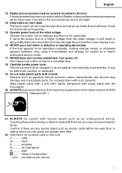
... parts near the tool's moving parts. If maintenance or servicing requires the removal of the tool. 8. NEVER use a power tool for applications other than those specified in place. Do not drop or throw the tool. NEVER operate this tool without all screws, bolts, and plates tightly mounted. Keep all guards or safety features in place and in place. Check their condition periodically. 12. Contact with bare hands after operation. 4. don't use tool...
... parts near the tool's moving parts. If maintenance or servicing requires the removal of the tool. 8. NEVER use a power tool for applications other than those specified in place. Do not drop or throw the tool. NEVER operate this tool without all screws, bolts, and plates tightly mounted. Keep all guards or safety features in place and in place. Check their condition periodically. 12. Contact with bare hands after operation. 4. don't use tool...
Instruction Manual
Page 7
... gasoline, thinner benzine, carbon tetrachloride, and alcohol may burn out. 16. hertz A amperes no load speed W watt Class II Construction ---/min ... Carefully handle power tools. Touching these active wiring or electric cable with soapy water and dry thoroughly. 20. no .......... Blades, cutting implements and accessories which is defective or operating abnormally. Check for symbols used on its nameplate. NEVER leave tool running unattended. revolutions...
... gasoline, thinner benzine, carbon tetrachloride, and alcohol may burn out. 16. hertz A amperes no load speed W watt Class II Construction ---/min ... Carefully handle power tools. Touching these active wiring or electric cable with soapy water and dry thoroughly. 20. no .......... Blades, cutting implements and accessories which is defective or operating abnormally. Check for symbols used on its nameplate. NEVER leave tool running unattended. revolutions...

Instruction Manual
Page 8
... the normal electrical safety precautions given in this power tool, and only genuine HITACHI replacement parts should disassemble or assemble this Instruction Manual, including not using the power tool in wet environments. otherwise the plastic may dissolve. Although this system has no external grounding, you must still follow these precautions: ⅜ Only HITACHI AUTHORIZED SERVICE CENTER should be installed. ⅜ Clean the exterior of this power tool, HITACHI has...
... the normal electrical safety precautions given in this power tool, and only genuine HITACHI replacement parts should disassemble or assemble this Instruction Manual, including not using the power tool in wet environments. otherwise the plastic may dissolve. Although this system has no external grounding, you must still follow these precautions: ⅜ Only HITACHI AUTHORIZED SERVICE CENTER should be installed. ⅜ Clean the exterior of this power tool, HITACHI has...
Instruction Manual
Page 9
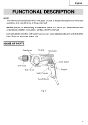
NEVER operate, or attempt any maintenance on your own power tool NAME OF PARTS Gear Cover Housing Nameplate Drill Chuck Side Handle Switch Trigger Handle Cover Push Button Stopper Fig. 1 9 English FUNCTIONAL DESCRIPTION NOTE: The information contained in this manual. Some illustrations in this Instruction Manual may show details or attachments that differ from those on the tool unless you in this Instruction Manual is designed to assist you have first read and understood all safety instructions contained in the safe operation and maintenance of the power tool.
NEVER operate, or attempt any maintenance on your own power tool NAME OF PARTS Gear Cover Housing Nameplate Drill Chuck Side Handle Switch Trigger Handle Cover Push Button Stopper Fig. 1 9 English FUNCTIONAL DESCRIPTION NOTE: The information contained in this manual. Some illustrations in this Instruction Manual may show details or attachments that differ from those on the tool unless you in this Instruction Manual is designed to assist you have first read and understood all safety instructions contained in the safe operation and maintenance of the power tool.
Instruction Manual
Page 10
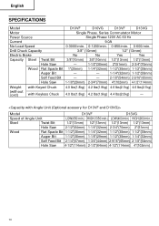
...) 1-1/2"(38mm) Self Feed Bit - - 2-1/8"(54mm) 2-9/16"(65mm) Hole Saw 1-1/8"(29mm) 2-3/4"(70mm) 4"(102mm) 4-1/2"(114mm) Weight with Keyed Chuck (without cord) with Keyless Chuck 4.0 lbs(1.8kg) 4.2 lbs(1.9kg) 4.6 lbs(2.1kg) 4.6 lbs(2.1kg) 4.0 lbs(1.8kg) 4.2 lbs(1.9kg) 4.4 lbs(2.0kg) - English SPECIFICATIONS Model D10VF D10VG D13VF D13VG Motor Single Phase, Series Commutator Motor Power Source Single Phase 120V AC 60 Hz Current 9.0A No-Load Speed 0-3000/min...
...) 1-1/2"(38mm) Self Feed Bit - - 2-1/8"(54mm) 2-9/16"(65mm) Hole Saw 1-1/8"(29mm) 2-3/4"(70mm) 4"(102mm) 4-1/2"(114mm) Weight with Keyed Chuck (without cord) with Keyless Chuck 4.0 lbs(1.8kg) 4.2 lbs(1.9kg) 4.6 lbs(2.1kg) 4.6 lbs(2.1kg) 4.0 lbs(1.8kg) 4.2 lbs(1.9kg) 4.4 lbs(2.0kg) - English SPECIFICATIONS Model D10VF D10VG D13VF D13VG Motor Single Phase, Series Commutator Motor Power Source Single Phase 120V AC 60 Hz Current 9.0A No-Load Speed 0-3000/min...
Instruction Manual
Page 11
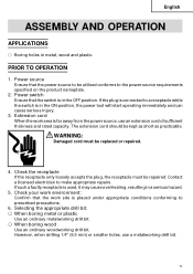
... Use an ordinary woodworking drill bit. The extension cord should be replaced or repaired. 4. WARNING: Damaged cord must be utilized conforms to make appropriate repairs. Contact a licensed electrician to the power source requirements specified on the product nameplate. 2. Check your work area is in metal, wood and plastic. English ASSEMBLY AND OPERATION APPLICATIONS ⅜ Boring holes in the ON position, the power tool will start operating...
... Use an ordinary woodworking drill bit. The extension cord should be replaced or repaired. 4. WARNING: Damaged cord must be utilized conforms to make appropriate repairs. Contact a licensed electrician to the power source requirements specified on the product nameplate. 2. Check your work area is in metal, wood and plastic. English ASSEMBLY AND OPERATION APPLICATIONS ⅜ Boring holes in the ON position, the power tool will start operating...
Instruction Manual
Page 12
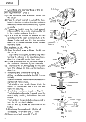
... clockwise direction. Tighten securely. (3) To remove the bit, place the chuck wrench into the socket on the body.) 10.Attaching the angle unit. (Optional accessory for right or left handed use. English 7. Check the rotational direction (Fig. 6) The bit rotates clockwise (viewed from drill (Fig. 7) 12 Drill chuck Chuck Wrench Tighten Loosen Fig. 2 Open End Wrench Loosen Fig. 3 Ring Sleeve Loosen Tighten Fig. 4 Loosen Side Handle Tighten Fig. 5 L mark Siwtch Trigger R mark Fig. 6 Mounting...
... clockwise direction. Tighten securely. (3) To remove the bit, place the chuck wrench into the socket on the body.) 10.Attaching the angle unit. (Optional accessory for right or left handed use. English 7. Check the rotational direction (Fig. 6) The bit rotates clockwise (viewed from drill (Fig. 7) 12 Drill chuck Chuck Wrench Tighten Loosen Fig. 2 Open End Wrench Loosen Fig. 3 Ring Sleeve Loosen Tighten Fig. 4 Loosen Side Handle Tighten Fig. 5 L mark Siwtch Trigger R mark Fig. 6 Mounting...
Instruction Manual
Page 13
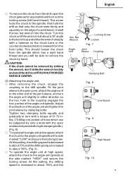
... the drill so that only the chuck rests firmly and squarely on the edge of the angle unit and tighten the joint sleeve by clamping bolts. Fit the joint sleeve to the gear cover, attach the angle unit to remove the chuck by hand. portion of the joint sleeve, and turn the angle unit slightly in turn out the locking screw (left hand thread). Bar Wrench Locking Screw Loosen Fig. 7 Angle Unit...
... the drill so that only the chuck rests firmly and squarely on the edge of the angle unit and tighten the joint sleeve by clamping bolts. Fit the joint sleeve to the gear cover, attach the angle unit to remove the chuck by hand. portion of the joint sleeve, and turn the angle unit slightly in turn out the locking screw (left hand thread). Bar Wrench Locking Screw Loosen Fig. 7 Angle Unit...
Instruction Manual
Page 14
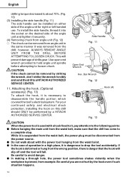
.... Be careful you are not hurt by a HITACHI AUTHORIZED SERVICE CENTER. This will fall. CAUTION: If the chuck cannot be performed by the hook even if such situation happens. 14 however, ALWAYS REMOVE ANGLE UNIT FROM THE DRILL BEFORE ATTEMPTING TO LOOSEN CHUCK. To install the side handle, thread it is used with the power tool hanging from the waist belot. ⅷ...
.... Be careful you are not hurt by a HITACHI AUTHORIZED SERVICE CENTER. This will fall. CAUTION: If the chuck cannot be performed by the hook even if such situation happens. 14 however, ALWAYS REMOVE ANGLE UNIT FROM THE DRILL BEFORE ATTEMPTING TO LOOSEN CHUCK. To install the side handle, thread it is used with the power tool hanging from the waist belot. ⅷ...
Instruction Manual
Page 15
... ineffective, send the tool to a HITACHI AUTHORIZED SERVICE CENTRE. 3. Drilling ⅜ When drilling, start again. This can be controlled by pulling the trigger again. 2. When the trigger is released, the tool stops. ⅜ The rotational speed of the hole. ⅜ If the drill stalls, release the trigger immediately, remove the bit from the receptacle when the drill bits and other various parts are installed or removed. Use enough pressure to keep drilling, but do not...
... ineffective, send the tool to a HITACHI AUTHORIZED SERVICE CENTRE. 3. Drilling ⅜ When drilling, start again. This can be controlled by pulling the trigger again. 2. When the trigger is released, the tool stops. ⅜ The rotational speed of the hole. ⅜ If the drill stalls, release the trigger immediately, remove the bit from the receptacle when the drill bits and other various parts are installed or removed. Use enough pressure to keep drilling, but do not...
Instruction Manual
Page 16
... the receptacle during maintenance and inspection. 1. Inspecting the carbon brushes For your continued safety and electrical shock protection, carbon brush inspection and replacement on this drill with oil or water. 6. Inspecting the screws Regularly inspect all service and repairs must be performed by a HITACHI AUTHORIZED SERVICE CENTER, ONLY. 16 WARNING: Using this tool should be loosened, retighten them immediately. Inspecting the drill bits Since use . Maintenance of the motor The motor unit winding...
... the receptacle during maintenance and inspection. 1. Inspecting the carbon brushes For your continued safety and electrical shock protection, carbon brush inspection and replacement on this drill with oil or water. 6. Inspecting the screws Regularly inspect all service and repairs must be performed by a HITACHI AUTHORIZED SERVICE CENTER, ONLY. 16 WARNING: Using this tool should be loosened, retighten them immediately. Inspecting the drill bits Since use . Maintenance of the motor The motor unit winding...

Parts List
Page 3
...,EUROPE CARBON BRUSH (1 PAIR) 2 INTERNAL WIRE (BROWN) 86L 1 FOR USA,CAN CHOKE COIL (BROWN) 110V 1 FOR GBR (110V) CHOKE COIL (BROWN) 220V-240V 1 FOR AUS,NZL,EUROPE PUSHING BUTTON 1 SWITCH (1P SCREW TYPE) W/LOCK 1 FOR USA,CAN SWITCH (1P SCREW TYPE) W/LOCK 1 FOR GBR (110V) SWITCH (1P SCREW TYPE) W/LOCK 1 FOR AUS,NZL,EUROPE TAPPING SCREW (W/FLANGE) D4X16 2 * ALTERNATIVE PARTS D 13VF --- 3 --- USED 1 REMARKS CHUCK WRENCH 13VLR-J 1 VINYL BAND 1 DRILL CHUCK 13VLR-J 1 INCLUD.2 DRILL CHUCK 13VLRD-N (W/O CHUCK WRENCH) 1 SPINDLE...
...,EUROPE CARBON BRUSH (1 PAIR) 2 INTERNAL WIRE (BROWN) 86L 1 FOR USA,CAN CHOKE COIL (BROWN) 110V 1 FOR GBR (110V) CHOKE COIL (BROWN) 220V-240V 1 FOR AUS,NZL,EUROPE PUSHING BUTTON 1 SWITCH (1P SCREW TYPE) W/LOCK 1 FOR USA,CAN SWITCH (1P SCREW TYPE) W/LOCK 1 FOR GBR (110V) SWITCH (1P SCREW TYPE) W/LOCK 1 FOR AUS,NZL,EUROPE TAPPING SCREW (W/FLANGE) D4X16 2 * ALTERNATIVE PARTS D 13VF --- 3 --- USED 1 REMARKS CHUCK WRENCH 13VLR-J 1 VINYL BAND 1 DRILL CHUCK 13VLR-J 1 INCLUD.2 DRILL CHUCK 13VLRD-N (W/O CHUCK WRENCH) 1 SPINDLE...

Parts List
Page 5
... COUPLING 609 986-142 JOINT SLEEVE 610 949-632 BOLT M8X45 (10 PCS.) 611 949-426 WASHER M8 (10 PCS.) 612 986-144 ANGLE HEAD ASS'Y 613 986-156 SPINDLE AND GEAR SET 614 949-168 WRENCH 13/17MM 615 317-676 HOOK (A) NO. CODE NO. CODE NO. USED REMARKS 1 INCLUD.603-614 2 1 1 2 1 1 1 1 2 2 1 INCLUD.602 1 1 1 8 -- 01 * ALTERNATIVE PARTS --- 5 --- STANDARD ACCESSORIES ITEM NO.
... COUPLING 609 986-142 JOINT SLEEVE 610 949-632 BOLT M8X45 (10 PCS.) 611 949-426 WASHER M8 (10 PCS.) 612 986-144 ANGLE HEAD ASS'Y 613 986-156 SPINDLE AND GEAR SET 614 949-168 WRENCH 13/17MM 615 317-676 HOOK (A) NO. CODE NO. CODE NO. USED REMARKS 1 INCLUD.603-614 2 1 1 2 1 1 1 1 2 2 1 INCLUD.602 1 1 1 8 -- 01 * ALTERNATIVE PARTS --- 5 --- STANDARD ACCESSORIES ITEM NO.

Parts List
Page 6
PARTS ITEM NO. USED REMARKS D 13VF --- 6 --- * ALTERNATIVE PARTS Printed in Japan 8 -- 01 (010821N) DESCRIPTION NO. CODE NO.
PARTS ITEM NO. USED REMARKS D 13VF --- 6 --- * ALTERNATIVE PARTS Printed in Japan 8 -- 01 (010821N) DESCRIPTION NO. CODE NO.


