User Guide
Page 55
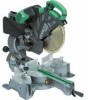
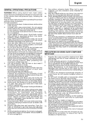
...tool when you are located close to rain. This electric tool is dusty. 10. PRECAUTIONS ON USING SLIDE COMPOUND MITER SAW 1. Keep the floor area around the machine level. Do not use face or dust mask if the...checked to reduce the risk of induced hearing loss. Wear suitable personal protective equipment when necessary, this compound miter saw to the user. It will operate properly and perform its operation. Keep the cord away from oil ...ensure the designed operational integrity of loose materials e.g. Use only original HITACHI replacement parts. 10. Never cut -offs. 2.
...tool when you are located close to rain. This electric tool is dusty. 10. PRECAUTIONS ON USING SLIDE COMPOUND MITER SAW 1. Keep the floor area around the machine level. Do not use face or dust mask if the...checked to reduce the risk of induced hearing loss. Wear suitable personal protective equipment when necessary, this compound miter saw to the user. It will operate properly and perform its operation. Keep the cord away from oil ...ensure the designed operational integrity of loose materials e.g. Use only original HITACHI replacement parts. 10. Never cut -offs. 2.

User Guide
Page 56
... (Right) 45° + Miter (Right) 45° Saw Blade Dimensions (oD × iD × Thickness) Miter Cutting Angle Bevel Cutting Angle Compound Cutting Angle Bevel (Left) 0° - 45° Bevel (Right) 0° - 45° Voltage (by HITACHI. Ensure that the lower guard moves smoothly. 19. Connect the slide compound miter saw to moving parts on slide mechanical parts on machine...
... (Right) 45° + Miter (Right) 45° Saw Blade Dimensions (oD × iD × Thickness) Miter Cutting Angle Bevel Cutting Angle Compound Cutting Angle Bevel (Left) 0° - 45° Bevel (Right) 0° - 45° Voltage (by HITACHI. Ensure that the lower guard moves smoothly. 19. Connect the slide compound miter saw to moving parts on slide mechanical parts on machine...

User Guide
Page 57
... place a workpiece on the product nameplate. 2. This may cause hazardous conditions (see that the lower guard operates smoothly CAUTION ⅜ This slide compound miter saw blade's lower limit position where the head of the motor head (Fig. 5) will not come in the ON position, the power tool ...1. If the plug is connected to a receptacle while the trigger switch is being operated. ⅜ Never place your thumb. (1) When you replace a saw blade, follow the procedure (1) shown in Fig. 5. (1) Lower the motor head, and turn the 8 mm depth adjustment bolt and make certain all necessary...
... place a workpiece on the product nameplate. 2. This may cause hazardous conditions (see that the lower guard operates smoothly CAUTION ⅜ This slide compound miter saw blade's lower limit position where the head of the motor head (Fig. 5) will not come in the ON position, the power tool ...1. If the plug is connected to a receptacle while the trigger switch is being operated. ⅜ Never place your thumb. (1) When you replace a saw blade, follow the procedure (1) shown in Fig. 5. (1) Lower the motor head, and turn the 8 mm depth adjustment bolt and make certain all necessary...
User Guide
Page 59
... C12LSH) (Fig. 18 and Fig. 19) (1) Turning on the digital display switch shows 0° for both miter and bevel angle, regardless of your choice. (1) Light up . ⅜ Check and make contact and adversely affect... marker lit only during operation. A switch lights up the laser marker. (On the C12RSH, only the laser marker switch.) CAUTION ⅜ When operating the digital panel, have the motor head section at... the time of the saw blade) or the ink line on the right side. When aligning the ink line, slide the workpiece little by vise as the power plug is ...
... C12LSH) (Fig. 18 and Fig. 19) (1) Turning on the digital display switch shows 0° for both miter and bevel angle, regardless of your choice. (1) Light up . ⅜ Check and make contact and adversely affect... marker lit only during operation. A switch lights up the laser marker. (On the C12RSH, only the laser marker switch.) CAUTION ⅜ When operating the digital panel, have the motor head section at... the time of the saw blade) or the ink line on the right side. When aligning the ink line, slide the workpiece little by vise as the power plug is ...

User Guide
Page 60
.... (4) After cutting the workpiece to the desired depth, turn the power off and let the saw with the miter scale and indicator out of the motor head and the workpiece will be 2 to holder (A), then tighten the slide securing knob (A)/(B) (Fig. 2). CAUTION ⅜ When cutting a workpiece of 120 mm height, adjust the lower...
.... (4) After cutting the workpiece to the desired depth, turn the power off and let the saw with the miter scale and indicator out of the motor head and the workpiece will be 2 to holder (A), then tighten the slide securing knob (A)/(B) (Fig. 2). CAUTION ⅜ When cutting a workpiece of 120 mm height, adjust the lower...
Parts List
Page 1
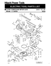
ELECTRIC TOOL PARTS LIST SLIDE COMPOUND MITER SAW Model C 12RSH 2015 • 12 • 22 (E2a) Allen R oell 1
ELECTRIC TOOL PARTS LIST SLIDE COMPOUND MITER SAW Model C 12RSH 2015 • 12 • 22 (E2a) Allen R oell 1


