Upgrading and Servicing Guide
Page 2
...without notice. The only warranties for Hewlett-Packard products and services are set forth in the United States by one or both of U.S. HP shall not be licensed in the express statements accompanying such products and services. Patents Nos. 4,930,158 and 4,930,160 until August 28, ... use or reliability of our products for the use of its software on equipment that is not furnished by copyright law. No part of HP. Nothing herein should be photocopied, reproduced, or translated to change without the prior written consent of this document may be construed as constituting...
...without notice. The only warranties for Hewlett-Packard products and services are set forth in the United States by one or both of U.S. HP shall not be licensed in the express statements accompanying such products and services. Patents Nos. 4,930,158 and 4,930,160 until August 28, ... use or reliability of our products for the use of its software on equipment that is not furnished by copyright law. No part of HP. Nothing herein should be photocopied, reproduced, or translated to change without the prior written consent of this document may be construed as constituting...

Upgrading and Servicing Guide
Page 3
... the Computer 7 Removing and Replacing Drives 8 Removing an optical drive 8 Adding or replacing an optical drive 9 Removing the HP Pocket Media Drive bay or hard disk drive 11 Adding or replacing the HP Pocket Media drive bay or hard disk drive 13 Removing the memory card reader 15 Adding or replacing the...
... the Computer 7 Removing and Replacing Drives 8 Removing an optical drive 8 Adding or replacing an optical drive 9 Removing the HP Pocket Media Drive bay or hard disk drive 11 Adding or replacing the HP Pocket Media drive bay or hard disk drive 13 Removing the memory card reader 15 Adding or replacing the...

Upgrading and Servicing Guide
Page 4
iv Table of Contents
iv Table of Contents

Upgrading and Servicing Guide
Page 5
Opening and Closing the Computer Upgrading and Servicing Guide 1 WARNING: Before you install and connect your computer. This Upgrading and Servicing Guide provides instructions for connection to an "IT" power system (an AC distribution system with no direct connection to the earth, according to the electrical power system, please read "Safety Information" in the Limited Warranty and Support Guide. Upgrading and Servicing Guide Safety Information This product has not been evaluated for removing and replacing the hardware components of your system to IEC 60950).
Opening and Closing the Computer Upgrading and Servicing Guide 1 WARNING: Before you install and connect your computer. This Upgrading and Servicing Guide provides instructions for connection to an "IT" power system (an AC distribution system with no direct connection to the earth, according to the electrical power system, please read "Safety Information" in the Limited Warranty and Support Guide. Upgrading and Servicing Guide Safety Information This product has not been evaluated for removing and replacing the hardware components of your system to IEC 60950).

Upgrading and Servicing Guide
Page 6
WARNING: Before you can safely handle it so that you remove the front and side panels of static electricity by briefly touching a grounded metal object. 2 Upgrading and Servicing Guide CAUTION: Static electricity can result in this information than to cool before opening the computer: 1 Remove any component in your computer, you must prepare it and the components. Ensure that you are discharged of the computer, always disconnect the modem cord from the telephone system, and then disconnect the computer from the power source. It is recommended that you use an antistatic ...
WARNING: Before you can safely handle it so that you remove the front and side panels of static electricity by briefly touching a grounded metal object. 2 Upgrading and Servicing Guide CAUTION: Static electricity can result in this information than to cool before opening the computer: 1 Remove any component in your computer, you must prepare it and the components. Ensure that you are discharged of the computer, always disconnect the modem cord from the telephone system, and then disconnect the computer from the power source. It is recommended that you use an antistatic ...

Upgrading and Servicing Guide
Page 7
WARNING: To reduce the risk of sharp edges inside the chassis. WARNING: Beware of electrical shock, fire, or damage to the equipment, do not plug telecommunications or telephone connectors into the network interface card (NIC) (labeled as an Ethernet connector). 2 Reconnect the modem/telephone cable and all other cables (such as the keyboard, mouse, and monitor cables). 3 Reconnect the external devices. 4 Turn on page 2. 2 Loosen the thumbscrew (A) that secures the side panel to the electrical outlet. Upgrading and Servicing Guide 3 After closing the computer: 1 Reconnect the ...
WARNING: To reduce the risk of sharp edges inside the chassis. WARNING: Beware of electrical shock, fire, or damage to the equipment, do not plug telecommunications or telephone connectors into the network interface card (NIC) (labeled as an Ethernet connector). 2 Reconnect the modem/telephone cable and all other cables (such as the keyboard, mouse, and monitor cables). 3 Reconnect the external devices. 4 Turn on page 2. 2 Loosen the thumbscrew (A) that secures the side panel to the electrical outlet. Upgrading and Servicing Guide 3 After closing the computer: 1 Reconnect the ...

Upgrading and Servicing Guide
Page 8
NOTE: There is a 3mm gap between the top of the side panel and the top of the chassis. Replacing the side panel 1 Align the tabs at the bottom of the side panel with the ridge on the bottom of the chassis when the side panel is attached properly. 2 Ensure that the hole for the thumbscrew is aligned with the hole in the proper position on page 3. 4 Upgrading and Servicing Guide Place the side panel in the chassis, and then replace the thumbscrew (A). 3 See "After closing the computer" on the chassis, and then slide it toward the front of the chassis.
NOTE: There is a 3mm gap between the top of the side panel and the top of the chassis. Replacing the side panel 1 Align the tabs at the bottom of the side panel with the ridge on the bottom of the chassis when the side panel is attached properly. 2 Ensure that the hole for the thumbscrew is aligned with the hole in the proper position on page 3. 4 Upgrading and Servicing Guide Place the side panel in the chassis, and then replace the thumbscrew (A). 3 See "After closing the computer" on the chassis, and then slide it toward the front of the chassis.
Upgrading and Servicing Guide
Page 9
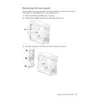
Upgrading and Servicing Guide 5 Removing the front panel This procedure is necessary only when removing or replacing an optical drive, memory card reader, HP Pocket Media Drive, or the hard disk drive. 1 Remove the HP Personal Media Drive, if present. 2 Pull the three tabs (B) away from the outside edge of the chassis. 3 Swing the front panel to the left (away from the chassis) to remove it.
Upgrading and Servicing Guide 5 Removing the front panel This procedure is necessary only when removing or replacing an optical drive, memory card reader, HP Pocket Media Drive, or the hard disk drive. 1 Remove the HP Personal Media Drive, if present. 2 Pull the three tabs (B) away from the outside edge of the chassis. 3 Swing the front panel to the left (away from the chassis) to remove it.
Upgrading and Servicing Guide
Page 10
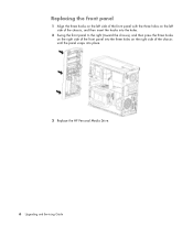
Replacing the front panel 1 Align the three hooks on the left side of the front panel with the three holes on the left side of the chassis, and then insert the hooks into the holes. 2 Swing the front panel to the right (toward the chassis), and then press the three hooks on the right side of the front panel into the three holes on the right side of the chassis until the panel snaps into place. 3 Replace the HP Personal Media Drive. 6 Upgrading and Servicing Guide
Replacing the front panel 1 Align the three hooks on the left side of the front panel with the three holes on the left side of the chassis, and then insert the hooks into the holes. 2 Swing the front panel to the right (toward the chassis), and then press the three hooks on the right side of the front panel into the three holes on the right side of the chassis until the panel snaps into place. 3 Replace the HP Personal Media Drive. 6 Upgrading and Servicing Guide
Upgrading and Servicing Guide
Page 11
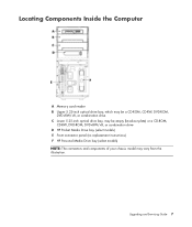
Upgrading and Servicing Guide 7 Locating Components Inside the Computer A Memory card reader B Upper 5.25-inch optical drive bay, which may be a CD-ROM, CD-RW, DVD-ROM, DVD+RW/+R, or combination drive C Lower 5.25-inch optical drive bay, may be empty (knockout plate) or a CD-ROM, CD-RW, DVD-ROM, DVD+RW/+R, or combination drive D HP Pocket Media Drive bay (select models) E Front connector panel (no replacement instructions) F HP Personal Media Drive bay (select models) NOTE: The connectors and components of your chassis model may vary from the illustration.
Upgrading and Servicing Guide 7 Locating Components Inside the Computer A Memory card reader B Upper 5.25-inch optical drive bay, which may be a CD-ROM, CD-RW, DVD-ROM, DVD+RW/+R, or combination drive C Lower 5.25-inch optical drive bay, may be empty (knockout plate) or a CD-ROM, CD-RW, DVD-ROM, DVD+RW/+R, or combination drive D HP Pocket Media Drive bay (select models) E Front connector panel (no replacement instructions) F HP Personal Media Drive bay (select models) NOTE: The connectors and components of your chassis model may vary from the illustration.

Upgrading and Servicing Guide
Page 12
CAUTION: Before you remove the hard disk drive, back up your computer. For details about the recovery procedure, see the user documentation that came with the operating system. IMPORTANT: Before adding a new optical drive, make sure you must run System Recovery using the recovery discs to load the factory-installed files. See "Opening and Closing the Computer" on page 7 for the optical drive to remove the side and front panels. Removing and Replacing Drives Your computer has several drives that you can add an optical drive into an empty lower optical drive bay. See "Locating ...
CAUTION: Before you remove the hard disk drive, back up your computer. For details about the recovery procedure, see the user documentation that came with the operating system. IMPORTANT: Before adding a new optical drive, make sure you must run System Recovery using the recovery discs to load the factory-installed files. See "Opening and Closing the Computer" on page 7 for the optical drive to remove the side and front panels. Removing and Replacing Drives Your computer has several drives that you can add an optical drive into an empty lower optical drive bay. See "Locating ...

Upgrading and Servicing Guide
Page 13
Parallel ATA drive Serial ATA drive 4 Pull the drive out through the front of the chassis. Discard the knockout plate. Adding or replacing an optical drive 1 If you are adding a drive to break the knockout plate out of the chassis. To do this, insert a flat-head screwdriver into the knockout plate slot (A), and then rotate the screwdriver to an empty lower optical drive bay, you must remove the knockout plate from the back of the optical drive that you are replacing an existing drive, remove it. See "Removing an optical drive" on page 8. 2 If you want to remove ...
Parallel ATA drive Serial ATA drive 4 Pull the drive out through the front of the chassis. Discard the knockout plate. Adding or replacing an optical drive 1 If you are adding a drive to break the knockout plate out of the chassis. To do this, insert a flat-head screwdriver into the knockout plate slot (A), and then rotate the screwdriver to an empty lower optical drive bay, you must remove the knockout plate from the back of the optical drive that you are replacing an existing drive, remove it. See "Removing an optical drive" on page 8. 2 If you want to remove ...

Upgrading and Servicing Guide
Page 14
Cable Select jumper 4 Release the drive bay by pulling the latch out, away from the illustration. 3 Make sure the jumper on the new optical drive is in the chassis.) 10 Upgrading and Servicing Guide Your drive may vary from the chassis, and then sliding the drive partway into the front of the chassis. (The latch drive brackets secure the drives in their respective positions in the CS (Cable Select) position.
Cable Select jumper 4 Release the drive bay by pulling the latch out, away from the illustration. 3 Make sure the jumper on the new optical drive is in the chassis.) 10 Upgrading and Servicing Guide Your drive may vary from the chassis, and then sliding the drive partway into the front of the chassis. (The latch drive brackets secure the drives in their respective positions in the CS (Cable Select) position.
Upgrading and Servicing Guide
Page 15
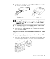
... into place. 7 Insert the drive latch pin fully into the hole labeled (2). 8 Replace the front and side panels, and then close the computer. Removing the HP Pocket Media Drive bay or hard disk drive 1 Prepare the computer to locate the hard disk drive and data may be opened, and then remove... and front panels. Parallel ATA drive Serial ATA drive WARNING: If you want to add. See "Opening and Closing the Computer" on page 1. 2 Release the HP Pocket Media Drive bay or hard disk drive by removing the two screws on page 1. Then slide the drive partway out of the front of...
... into place. 7 Insert the drive latch pin fully into the hole labeled (2). 8 Replace the front and side panels, and then close the computer. Removing the HP Pocket Media Drive bay or hard disk drive 1 Prepare the computer to locate the hard disk drive and data may be opened, and then remove... and front panels. Parallel ATA drive Serial ATA drive WARNING: If you want to add. See "Opening and Closing the Computer" on page 1. 2 Release the HP Pocket Media Drive bay or hard disk drive by removing the two screws on page 1. Then slide the drive partway out of the front of...

Upgrading and Servicing Guide
Page 16
Pocket Media Drive Parallel ATA drive Serial ATA drive 4 Pull the drive out through the front of the drive by squeezing the two latches on each and pulling the cable. 3 Disconnect the power and data cables from the back of the chassis. 12 Upgrading and Servicing Guide
Pocket Media Drive Parallel ATA drive Serial ATA drive 4 Pull the drive out through the front of the drive by squeezing the two latches on each and pulling the cable. 3 Disconnect the power and data cables from the back of the chassis. 12 Upgrading and Servicing Guide

Upgrading and Servicing Guide
Page 17
... HDD. For a hard disk drive, make sure to insert the screws into the holes labeled (2). Adding or replacing the HP Pocket Media drive bay or hard disk drive 1 If replacing an existing HP Pocket Media Drive bay or hard disk drive, remove it locks into place. 3 Align the two screw holes on... the chassis with the two screw holes on page 11. 2 Slide the new HP Pocket Media Drive bay or hard disk drive into the front of the chassis until it . See "Removing the...
... HDD. For a hard disk drive, make sure to insert the screws into the holes labeled (2). Adding or replacing the HP Pocket Media drive bay or hard disk drive 1 If replacing an existing HP Pocket Media Drive bay or hard disk drive, remove it locks into place. 3 Align the two screw holes on... the chassis with the two screw holes on page 11. 2 Slide the new HP Pocket Media Drive bay or hard disk drive into the front of the chassis until it . See "Removing the...
Upgrading and Servicing Guide
Page 18
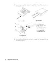
Pocket Media Drive Serial ATA drive A - Connect to the computer motherboard. B - Connect to a secondary hard disk drive (select models only). C - Parallel ATA drive 5 Replace the front and side panels, and close the computer. Connect to the back of the HP Pocket Media Drive bay or hard disk drive. See "Opening and Closing the Computer" on page 1. 14 Upgrading and Servicing Guide 4 Connect the power and data cables to a primary hard disk drive.
Pocket Media Drive Serial ATA drive A - Connect to the computer motherboard. B - Connect to a secondary hard disk drive (select models only). C - Parallel ATA drive 5 Replace the front and side panels, and close the computer. Connect to the back of the HP Pocket Media Drive bay or hard disk drive. See "Opening and Closing the Computer" on page 1. 14 Upgrading and Servicing Guide 4 Connect the power and data cables to a primary hard disk drive.

Upgrading and Servicing Guide
Page 19
Upgrading and Servicing Guide 15 Removing the memory card reader 1 Prepare the computer to loosen it, and then pulling it partway out of the front of the chassis. 3 Disconnect the cables from the back of the memory card reader. 4 Pull the memory card reader out of the front of the chassis. See "Opening and Closing the Computer" on page 1. 2 Release the drive by removing the screw on the top of the memory card reader, sliding the memory card reader to the left to be opened, and then remove the side and front panels.
Upgrading and Servicing Guide 15 Removing the memory card reader 1 Prepare the computer to loosen it, and then pulling it partway out of the front of the chassis. 3 Disconnect the cables from the back of the memory card reader. 4 Pull the memory card reader out of the front of the chassis. See "Opening and Closing the Computer" on page 1. 2 Release the drive by removing the screw on the top of the memory card reader, sliding the memory card reader to the left to be opened, and then remove the side and front panels.

Upgrading and Servicing Guide
Page 20
See "Opening and Closing the Computer" on the top of the memory card reader, and then insert the short screw to secure the memory card reader to remove the memory card reader, if necessary. Adding or replacing the memory card reader 1 Complete the procedures to the chassis. 5 Replace the front and side panels, and close the computer. See "Removing the memory card reader" on page 15. 2 Slide the memory card reader partway into the front of the chassis. 3 Attach the cables to the back of the memory card reader. 4 Push the memory card reader into the chassis until the screw hole on the ...
See "Opening and Closing the Computer" on the top of the memory card reader, and then insert the short screw to secure the memory card reader to remove the memory card reader, if necessary. Adding or replacing the memory card reader 1 Complete the procedures to the chassis. 5 Replace the front and side panels, and close the computer. See "Removing the memory card reader" on page 15. 2 Slide the memory card reader partway into the front of the chassis. 3 Attach the cables to the back of the memory card reader. 4 Push the memory card reader into the chassis until the screw hole on the ...

Upgrading and Servicing Guide
Page 21
Removing the hard disk drive 1 Prepare the computer to push down the latch on its side. 3 Remove the two screws that secure the hard disk drive cage to the chassis. 4 Use a screwdriver to be opened, and then remove the side and front panels. See "Opening and Closing the Computer" on page 1. 2 Gently lay the computer on the side of the hard disk drive cage, and then slide the hard disk drive cage away from the bottom of the chassis. Upgrading and Servicing Guide 17
Removing the hard disk drive 1 Prepare the computer to push down the latch on its side. 3 Remove the two screws that secure the hard disk drive cage to the chassis. 4 Use a screwdriver to be opened, and then remove the side and front panels. See "Opening and Closing the Computer" on page 1. 2 Gently lay the computer on the side of the hard disk drive cage, and then slide the hard disk drive cage away from the bottom of the chassis. Upgrading and Servicing Guide 17