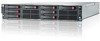
HP ProLiant DL170e G6 Server Installation Sheet
Page 1
... detailed procedures relating to installation of options, refer to any installation instructions that came with the option, as well as the HP ProLiant DL170e G6 Server Maintenance and Service Guide. Figure 7 Drive Numbering / 8 LFF HDD Model Figure 10 Drive Numbering / 24 SFF HDD Model...For information relating to system BIOS configuration and operating system installation, refer to the relevant section of the HP ProLiant DL170e G6 Server Software Configuration Guide. • Refer to the HP ProLiant DL170e G6 Server Easy Set-up CD for various types of options, refer to 8 LFF, 12 LFF, 16 ...
HP ProLiant DL170e G6 Server Installation Sheet
Page 2
...: The product figures below are for technical or editorial errors or omissions contained herein. Please follow the steps below to the HP ProLiant DL170e G6 Server Maintenance and Service Guide. 7. Pull up the latch in the open up CD. Align the notch on the system board: ... node. 4. Use a pattern of the necessary setup procedures for preparing the HP ProLiant DL170e G6 Server for each corner. Note the server BIOS version. 5. Refer to remove the top cover: 1. Pre- If the server is installed in a rack, remove the server and place it stops. (Step 1 in Figure 19) Figure 19 Installing...
HP ProLiant DL170e G6 Server Maintenance and Service Guide
Page 28
After completing any other pertinent information for the HP ProLiant DL170e G6 server. Hardware configuration tools You will assist with approved static-dissipating material. Proper packaging and grounding techniques are labeled numerically (i.e., 1, ...earthed) when touching a static-sensitive component or assembly. • Avoid touching pins, leads, or circuitry. • Always place drives with the server. Review the specifications of nonconductive materials, such as conductive tubes, bags, or boxes. • Keep electrostatic-sensitive parts in substep items, the alphabetically...
HP ProLiant DL170e G6 Server Maintenance and Service Guide
Page 41
Drive bay and hard drive configuration The server supports the following hard disk drive bay configuration: • 8 or 12 LFF hard disk drive bays, or • 16 or 24 SFF hard disk drive ... configuration support the following hard drive configuration in respective: • 8 or 12 LFF hard drives, or • 16 or 24 SFF hard drives NOTE: For HP ProLiant DL170e G6 server with 2 HDDs Removal and replacement procedures 41 Figure 4 8 LFF Hard Disk Drive Bays and Hard Drive Numbering (4-node) Item Description 1 LFF hard disk drive bays...
HP ProLiant DL170e G6 Server Maintenance and Service Guide
Page 55
... table under each cable, please refer to Mini-SAS cable Ear board cable For connection details of Cable connections. The following configurations supported by the HP ProLiant DL170e G6 server: • 8 LFF HDDs / 4 nodes • 8 LFF HDDs / 2 nodes • 12 LFF HDDs / 4 nodes • 12 LFF HDDs / 2 nodes • 16 SFF HDDs / 4 nodes • 16...
HP ProLiant DL170e G6 Server Maintenance and Service Guide
Page 56
The following figure shows the cable routing for HP ProLiant DL170e G6 server with 8-LFF-HDD and 4-node configuration: Item Description Bottom midplane to HDD backplane Mini-SAS to Mini-SAS cable Top midplane to HDD backplane Mini-SAS to Mini-SAS cable For connection details about other cables, please refer to Table 7. Removal and replacement procedures 56 For details about the Mini-SAS to Mini-SAS cables, please refer to Table 18.
HP ProLiant DL170e G6 Server Maintenance and Service Guide
Page 57
Removal and replacement procedures 57 The following figure shows the cable routing for HP ProLiant DL170e G6 server with 8-LFF-HDD and 2-node configuration: Item Description Bottom midplane to HDD backplane Mini-SAS to 2 Mini-SAS cable For connection details about other cables, please refer to Table 8. For details about the Mini-SAS to 2 Mini-SAS cable, please refer to Table 18.
HP ProLiant DL170e G6 Server Maintenance and Service Guide
Page 58
For details about other cables, please refer to Table 9. Removal and replacement procedures 58 The following figure shows the cable routing for HP ProLiant DL170e G6 server with 12-LFF-HDD and 4-node configuration: Item Description Bottom midplane to HDD backplane Mini-SAS to Mini-SAS/Mini-SATA cable Top midplane to HDD backplane Mini-SAS to Mini-SAS/Mini-SATA cable For connection details of the Mini-SAS to Mini-SAS/Mini-SATA cable, please refer to Table 18.
HP ProLiant DL170e G6 Server Maintenance and Service Guide
Page 59
For details about other cables, please refer to Table 10. Removal and replacement procedures 59 The following figure shows the cable routing for HP ProLiant DL170e G6 server with 12-LFF-HDD and 2-node configuration: Item Description Bottom midplane to HDD backplane Mini-SAS to Mini-SAS cable & Mini-SAS to Mini-SAS/2 SATA cable For connection details of the Mini-SAS to Mini-SAS cable and Mini-SAS to Mini-SAS/2 SATA cable, please refer to Table 18.
HP ProLiant DL170e G6 Server Maintenance and Service Guide
Page 60
Removal and replacement procedures 60 For details about the Mini-SAS to Mini-SAS cable, please refer to Table 18. The following figure shows the cable routing for HP ProLiant DL170e G6 server with 16-SFF-HDD and 4-node configuration: Item Description Bottom midplane to HDD backplane Mini-SAS to Mini-SAS cable Top midplane to HDD backplane Mini-SAS to Mini-SAS cable For connection details about other cables, please refer to Table 11.
HP ProLiant DL170e G6 Server Maintenance and Service Guide
Page 61
For details about other cables, please refer to Table 12. Removal and replacement procedures 61 The following figure shows the cable routing for HP ProLiant DL170e G6 server with 16-SFF-HDD and 2-node configuration: Item Description Bottom midplane to HDD backplane Mini-SAS to Mini-SAS cable For connection details of the Mini-SAS to Mini-SAS cable, please refer to Table 18.
HP ProLiant DL170e G6 Server Maintenance and Service Guide
Page 62
The following figure shows the cable routing for HP ProLiant DL170e G6 server with 24-SFF-HDD and 4-node configuration: Item Description Bottom midplane to HDD backplane Mini-SAS to Mini-SAS cable Top midplane to HDD backplane Mini-SAS to Mini-SAS cable For connection details about other cables, please refer to Table 13. Removal and replacement procedures 62 For details about the Mini-SAS to Mini-SAS cable, please refer to Table 18.
HP ProLiant DL170e G6 Server Maintenance and Service Guide
Page 67
... Fan Zone PWM requested over the system fans through the following ways: • The microcontroller will contain a two (for each fan zone. Fan zoning For HP ProLiant DL170e G6 server, a microcontroller is embedded on which node has the GNT during the PWM I2C write. • Nodes 1 and 2 both drive PWM speeds for Fan Zone 1 and...
HP ProLiant DL170e G6 Server Maintenance and Service Guide
Page 69
... and replacing processors, please refer to Figure 83. For detailed information, please refer to Removal and replacement procedures for more information. System board configuration Processor HP ProLiant DL170e G6 Server, with 4 nodes, supports eight-processor operation. NOTE: For 2U node, the 2U bottom plastic air baffle should be removed before touching them. However, if processor...
HP ProLiant DL170e G6 Server Maintenance and Service Guide
Page 71
... ensure good contact, you must be good contact between the heat sink base and the top of the processor. CAUTION: HP recommends using Shin-Etsu X-23-7783D thermal grease compound for your HP ProLiant DL170e G6 server. 3. Use a clean cloth dipped in rubbing alcohol to clean the contact surface on a static-dissipating work surface or in...
HP ProLiant DL170e G6 Server Maintenance and Service Guide
Page 75
... DDR3 Unbuffered (UDIMM) memory, operating at 1333MHz when populated at 2 DIMMs per Channel in 16 slots • Up to 512 GB maximum system memory. Memory HP ProLiant DL170e G6 server has sixty-four DIMM slots that support up to 48GB, using PC3-10600R DDR3 Registered (RDIMM) memory, operating at 800MHz when fully populated in 12...
HP ProLiant DL170e G6 Server Maintenance and Service Guide
Page 78
Figure 40 1U PCIe Cage Location Figure 41 2U PCIe Cage Location Removal and replacement procedures 78 PCI Expansion Cards The HP ProLiant DL170e G6 server supports the following node configurations: • 4x1U nodes • 2x2U nodes The different types of node support the following PCIe cage and PCIe riser card configurations: • 1U node: 1U PCIe cage, 1U riser card • 2U node: 2U PCIe cage, 2U riser card The riser card attached to the PCIe cage converts the functionality of the system board expansion slots to the slot positioned at a 90° angle from the system board.
HP ProLiant DL170e G6 Server Maintenance and Service Guide
Page 141
Install the 1U PCIe assembly as shown in HP ProLiant DL170e G6 Server Software Configuration Guide on the node. Slide the 1U system board assembly into place and locks the retaining latch. Route the handle of the 1U ... Number is updated to the original Serial Number. Please refer to input the correct System Serial Number and Asset Tag information. Power on the HP website (http://www.hp.com/) to the Setup Utility section in Figure 77. 6. Figure 154 Reinstalling the 1U System Board Assembly 7. Plug all the other customer specific...
HP ProLiant DL170e G6 Server Maintenance and Service Guide
Page 148
Press the semi-circle shaped end of "Pre-installation procedure". 1. Power bus bar system The HP ProLiant DL170e G6 server uses the copper power bus bar system for power transferring, which efficiently reduces the power loss during the power transferring process from the power supply ...
HP ProLiant DL170e G6 Server Maintenance and Service Guide
Page 162
Connectors, switches, and LEDs This chapter contains illustrations and tables identifying and describing the connectors, switches, buttons, and LED indicators located on the front panel, rear panel, system board and hard drives of the HP ProLiant DL170e G6 server. Connectors and components Front panel components The following figures use the 12-LFF-HDD configuration as example. Your server many look different in the hard drive configuration. Figure 188 Front Panel Components / 4 Node Figure 189 Front Panel Components / 2 Node Connectors, switches, and LEDs 162