
Start Here Guide
Page 15
...: 1 Click the Windows Start Button® on your computer. NOTE: Some peripheral devices are not included with the 6-pin FireWire (IEEE 1394) connector on the taskbar, and then click Control Panel. 2 Click System and Maintenance, and then click System. 3 Click Device Manager. 4 Click the plus sign (+) next to the camera port. These...
...: 1 Click the Windows Start Button® on your computer. NOTE: Some peripheral devices are not included with the 6-pin FireWire (IEEE 1394) connector on the taskbar, and then click Control Panel. 2 Click System and Maintenance, and then click System. 3 Click Device Manager. 4 Click the plus sign (+) next to the camera port. These...

Start Here Guide
Page 25
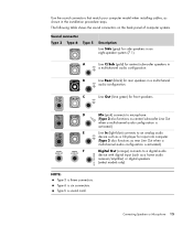
... speakers in a multichannel audio configuration. B Line Rear (black) for side speakers in the installation procedure steps. The following table shows the sound connectors on the back panel of computer systems. Sound connector Type 3 Type 6 Type S Description Line Side (gray) for rear speakers in a multichannel audio configuration. Type 6 is sound card. Connecting Speakers or...
... speakers in a multichannel audio configuration. B Line Rear (black) for side speakers in the installation procedure steps. The following table shows the sound connectors on the back panel of computer systems. Sound connector Type 3 Type 6 Type S Description Line Side (gray) for rear speakers in a multichannel audio configuration. Type 6 is sound card. Connecting Speakers or...
Start Here Guide
Page 35
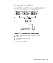
IN OUT 2.1 home stereo installation The following diagram shows a typical two-channel (2.1 speaker) installation that uses passive stereo speakers and plugs into a home stereo standard left and right) Connecting Speakers or Microphone 29 Your system may be different. Back Sub E C DE Computer to 2.1 multichannel audio system connection A Computer back-panel connectors (type 3, type 6, or sound card) B Y adapter cables C Receiver/amplifier (audio input jacks) D Subwoofer E Front speakers (left and right input. A B Center C Front Surr. This is only a suggested configuration.
IN OUT 2.1 home stereo installation The following diagram shows a typical two-channel (2.1 speaker) installation that uses passive stereo speakers and plugs into a home stereo standard left and right) Connecting Speakers or Microphone 29 Your system may be different. Back Sub E C DE Computer to 2.1 multichannel audio system connection A Computer back-panel connectors (type 3, type 6, or sound card) B Y adapter cables C Receiver/amplifier (audio input jacks) D Subwoofer E Front speakers (left and right input. A B Center C Front Surr. This is only a suggested configuration.

Start Here Guide
Page 36
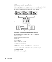
A B Center C Front Surr. This is only a suggested configuration. Your system may be different. Back Sub F E C D G Computer to 5.1 multichannel audio system connection A Computer back-panel connectors (type 3, type 6, or sound card) B Y adapter cables C Receiver/amplifier (audio input jacks) D Subwoofer E Center speaker F Front speakers (left and right) G Rear speakers (left and right) 5.1 ...
A B Center C Front Surr. This is only a suggested configuration. Your system may be different. Back Sub F E C D G Computer to 5.1 multichannel audio system connection A Computer back-panel connectors (type 3, type 6, or sound card) B Y adapter cables C Receiver/amplifier (audio input jacks) D Subwoofer E Center speaker F Front speakers (left and right) G Rear speakers (left and right) 5.1 ...

Start Here Guide
Page 38
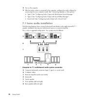
... that requires multichannel inputs on the computer. 9 After the audio system is only a suggested configuration. This is connected to 7.1 multichannel audio system connection A Computer back-panel connectors (type 3, type 6, or sound card) B Y adapter cables C Receiver/amplifier (audio input jacks) D Subwoofer E Center speaker F Front speakers (left and right) G Rear speakers (left and right...
... that requires multichannel inputs on the computer. 9 After the audio system is only a suggested configuration. This is connected to 7.1 multichannel audio system connection A Computer back-panel connectors (type 3, type 6, or sound card) B Y adapter cables C Receiver/amplifier (audio input jacks) D Subwoofer E Center speaker F Front speakers (left and right) G Rear speakers (left and right...

Start Here Guide
Page 40
...the white stereo plug. Type 6: See "Configuring Audio Output with Multichannel Sound Manager." Connect the red RCA stereo plug on the back panel. Connecting Digital Audio (Select models only) If you have a center/subwoofer speaker, connect the stereo mini-jack of a Y adapter cable ...into the microphone (pink) connector or the center speaker/subwoofer (gold) connector that the Y adapter cables are connecting your computer. 3 6 S Connect the left and right ends of the Y adapter cable ...
...the white stereo plug. Type 6: See "Configuring Audio Output with Multichannel Sound Manager." Connect the red RCA stereo plug on the back panel. Connecting Digital Audio (Select models only) If you have a center/subwoofer speaker, connect the stereo mini-jack of a Y adapter cable ...into the microphone (pink) connector or the center speaker/subwoofer (gold) connector that the Y adapter cables are connecting your computer. 3 6 S Connect the left and right ends of the Y adapter cable ...
Start Here Guide
Page 41
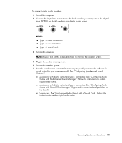
...." Follow the instructions to the computer, configure the audio software for sound output for your computer to enable digital audio output. Type S is six connectors. Follow the instructions to the digital input (S/PDIF) on digital speakers or a digital audio system. 3 6 S NOTE: Type 3 is already enabled... 35 Sound card: See "Configuring Audio Output with Multichannel Sound Manager." Audio card with digital output and type 3 connectors: See "Configuring Audio Output with a Sound Card." To connect digital audio speakers: 1 Turn off the computer. 2 Connect the Digital Out...
...." Follow the instructions to the computer, configure the audio software for sound output for your computer to enable digital audio output. Type S is six connectors. Follow the instructions to the digital input (S/PDIF) on digital speakers or a digital audio system. 3 6 S NOTE: Type 3 is already enabled... 35 Sound card: See "Configuring Audio Output with Multichannel Sound Manager." Audio card with digital output and type 3 connectors: See "Configuring Audio Output with a Sound Card." To connect digital audio speakers: 1 Turn off the computer. 2 Connect the Digital Out...
Start Here Guide
Page 48
...; If you are using a cable or satellite set-top box, you are using a TV antenna or standard cable connector, the signal is routed to the second set -top box to both TV sources must connect a second set of ...not available in Windows Media Center, so both tuners internally. If you are using a TV antenna or standard cable connector, the signal is routed to control the television channels. The computer supports two tuner configurations: TV Tuner Single-tuner TV... two satellite TV sources, they must be of inputs. Otherwise, connect a second set of back-panel connectors.
...; If you are using a cable or satellite set-top box, you are using a TV antenna or standard cable connector, the signal is routed to the second set -top box to both TV sources must connect a second set of ...not available in Windows Media Center, so both tuners internally. If you are using a TV antenna or standard cable connector, the signal is routed to control the television channels. The computer supports two tuner configurations: TV Tuner Single-tuner TV... two satellite TV sources, they must be of inputs. Otherwise, connect a second set of back-panel connectors.

Start Here Guide
Page 69
... connecting the remote sensor 43 connecting the TV signal source 41 connecting TV signal source with set-top box and VCR 45 front-panel connectors 2 Help & Tools 60 setting up 1 Index connecting devices 9 digital camera 8 digital video camera 8 dual tuner 42 DVI device 55 HDMI... 52 peripherals 2 Standard TV 56 Standard video 56 S-video 57 Connecting more than one display 50 connection modem 15 wired network 12 connector Audio Line In 6 Audio Line Out 6 back panel 8 Composite Video In 6 computer 2 FireWire (IEEE 1394) 5 FM In 7 headphones 4 keyboard 5 Microphone In 4 modem 7 monitor 6 mouse 5 ...
... connecting the remote sensor 43 connecting the TV signal source 41 connecting TV signal source with set-top box and VCR 45 front-panel connectors 2 Help & Tools 60 setting up 1 Index connecting devices 9 digital camera 8 digital video camera 8 dual tuner 42 DVI device 55 HDMI... 52 peripherals 2 Standard TV 56 Standard video 56 S-video 57 Connecting more than one display 50 connection modem 15 wired network 12 connector Audio Line In 6 Audio Line Out 6 back panel 8 Composite Video In 6 computer 2 FireWire (IEEE 1394) 5 FM In 7 headphones 4 keyboard 5 Microphone In 4 modem 7 monitor 6 mouse 5 ...
Upgrading and Servicing Guide
Page 7
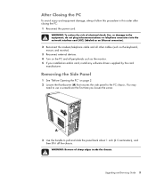
... electrical shock, fire, or damage to pull and slide the panel back about 1 inch (2.5 centimeters), and then lift it off the chassis. You may need to the PC chassis. Removing the Side Panel 1 See "Before Opening the PC" on the PC and all peripherals such as the keyboard, mouse, and monitor... the PC: 1 Reconnect the power cord. After Closing the PC To avoid injury and equipment damage, always follow this procedure in card, install any software drivers supplied by the card manufacturer. A 3 Use the handle to the equipment, do not plug telecommunications or telephone connectors into ...
... electrical shock, fire, or damage to pull and slide the panel back about 1 inch (2.5 centimeters), and then lift it off the chassis. You may need to the PC chassis. Removing the Side Panel 1 See "Before Opening the PC" on the PC and all peripherals such as the keyboard, mouse, and monitor... the PC: 1 Reconnect the power cord. After Closing the PC To avoid injury and equipment damage, always follow this procedure in card, install any software drivers supplied by the card manufacturer. A 3 Use the handle to the equipment, do not plug telecommunications or telephone connectors into ...

Upgrading and Servicing Guide
Page 11
... empty (knockout plate) or a CD-ROM, CD-RW, DVD-ROM, DVD+RW/+R, combination drive, or HP Personal Media Drive bay (select models) D HP Pocket Media Drive bay, a hard disk drive, or a diskette (floppy) drive (select models) E Front connector panel (no replacement instructions) F Hard disk drive and space for a second hard disk drive (located inside...
... empty (knockout plate) or a CD-ROM, CD-RW, DVD-ROM, DVD+RW/+R, combination drive, or HP Personal Media Drive bay (select models) D HP Pocket Media Drive bay, a hard disk drive, or a diskette (floppy) drive (select models) E Front connector panel (no replacement instructions) F Hard disk drive and space for a second hard disk drive (located inside...
Upgrading and Servicing Guide
Page 30
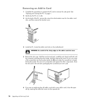
...add-in the anti-static packaging that contained your new card. See "Opening and Closing the PC" on page 1. 2 Gently lay the PC on its side. 3 On the back of the sharp edges on the motherboard. WARNING: Be careful ...of the PC, remove the screw from the socket, and then remove the card. Be sure not to break...slot cover. Hold the card at each end, carefully rock it back and forth until the connectors pull free from the bracket cover for the add-in card slots, and then remove the bracket cover. 4 Inside the...
...add-in the anti-static packaging that contained your new card. See "Opening and Closing the PC" on page 1. 2 Gently lay the PC on its side. 3 On the back of the sharp edges on the motherboard. WARNING: Be careful ...of the PC, remove the screw from the socket, and then remove the card. Be sure not to break...slot cover. Hold the card at each end, carefully rock it back and forth until the connectors pull free from the bracket cover for the add-in card slots, and then remove the bracket cover. 4 Inside the...
Upgrading and Servicing Guide
Page 31
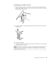
The whole connector should be seated properly in the card slot. 2 On the back of the add-in card with the slot on page 1. Upgrading and Servicing Guide 27 See "Opening and Closing the PC" on the chassis and gently but firmly press the card straight down into the add-in card slots.... 3 Set the chassis upright. 4 Complete the procedures to the card, power supply, keyboard, and monitor. Installing an Add-in Card 1 Align the edge of the PC, replace the bracket cover for the add-in card slot. NOTE: If the new card or device isn't working, read through the card manufacturer's installation...
The whole connector should be seated properly in the card slot. 2 On the back of the add-in card with the slot on page 1. Upgrading and Servicing Guide 27 See "Opening and Closing the PC" on the chassis and gently but firmly press the card straight down into the add-in card slots.... 3 Set the chassis upright. 4 Complete the procedures to the card, power supply, keyboard, and monitor. Installing an Add-in Card 1 Align the edge of the PC, replace the bracket cover for the add-in card slot. NOTE: If the new card or device isn't working, read through the card manufacturer's installation...

Getting Started Guide
Page 13
... included with your device. NOTE: You must use a 6-pin (not a 4-pin) FireWire (IEEE 1394) cable with the 6-pin FireWire (IEEE 1394) connector on the taskbar, and then click Control Panel. 2 Click System and Maintenance, and then click System. 3 Click Device Manager. 4 Click the plus sign (+) next to the camera port. Unplug the...
... included with your device. NOTE: You must use a 6-pin (not a 4-pin) FireWire (IEEE 1394) cable with the 6-pin FireWire (IEEE 1394) connector on the taskbar, and then click Control Panel. 2 Click System and Maintenance, and then click System. 3 Click Device Manager. 4 Click the plus sign (+) next to the camera port. Unplug the...
Getting Started Guide
Page 23
... a home audio receiver/amplifier) or digital speakers (select models only). Connecting Speakers or Microphone 15 NOTE: Type 3 is six connectors. The following table shows the sound connectors on the back panel of computer systems. Sound connector Type 3 Type 6 Type S Description Line Side (gray) for center/subwoofer speakers in an eight-speaker system (7.1). A Line C/Sub...
... a home audio receiver/amplifier) or digital speakers (select models only). Connecting Speakers or Microphone 15 NOTE: Type 3 is six connectors. The following table shows the sound connectors on the back panel of computer systems. Sound connector Type 3 Type 6 Type S Description Line Side (gray) for center/subwoofer speakers in an eight-speaker system (7.1). A Line C/Sub...

Getting Started Guide
Page 33
IN OUT 2.1 home stereo installation The following diagram shows a typical two-channel (2.1 speaker) installation that uses passive stereo speakers and plugs into a home stereo standard left and right) Connecting Speakers or Microphone 25 This is only a suggested configuration. Back Sub E C DE Computer to 2.1 multichannel audio system connection A Computer back-panel connectors (type 3, type 6, or sound card) B Y adapter cables C Receiver/amplifier (audio input jacks) D Subwoofer E Front speakers (left and right input. Your system may be different. A B Center C Front Surr.
IN OUT 2.1 home stereo installation The following diagram shows a typical two-channel (2.1 speaker) installation that uses passive stereo speakers and plugs into a home stereo standard left and right) Connecting Speakers or Microphone 25 This is only a suggested configuration. Back Sub E C DE Computer to 2.1 multichannel audio system connection A Computer back-panel connectors (type 3, type 6, or sound card) B Y adapter cables C Receiver/amplifier (audio input jacks) D Subwoofer E Front speakers (left and right input. Your system may be different. A B Center C Front Surr.
Getting Started Guide
Page 34
This is only a suggested configuration. Back Sub F E C D G Computer to 5.1 multichannel audio system connection A Computer back-panel connectors (type 3, type 6, or sound card) B Y adapter cables C Receiver/amplifier (audio input jacks) D Subwoofer E Center speaker F Front speakers (left and right) G Rear speakers (left and right) 5.1 ...
This is only a suggested configuration. Back Sub F E C D G Computer to 5.1 multichannel audio system connection A Computer back-panel connectors (type 3, type 6, or sound card) B Y adapter cables C Receiver/amplifier (audio input jacks) D Subwoofer E Center speaker F Front speakers (left and right) G Rear speakers (left and right) 5.1 ...
Getting Started Guide
Page 36
... that requires multichannel inputs on the computer. 9 After the audio system is only a suggested configuration. This is connected to 7.1 multichannel audio system connection A Computer back-panel connectors (type 3, type 6, or sound card) B Y adapter cables C Receiver/amplifier (audio input jacks) D Subwoofer E Center speaker F Front speakers (left and right) G Rear speakers (left and right...
... that requires multichannel inputs on the computer. 9 After the audio system is only a suggested configuration. This is connected to 7.1 multichannel audio system connection A Computer back-panel connectors (type 3, type 6, or sound card) B Y adapter cables C Receiver/amplifier (audio input jacks) D Subwoofer E Center speaker F Front speakers (left and right) G Rear speakers (left and right...

Getting Started Guide
Page 38
...Audio Output with a Sound Card." Connecting Digital Audio (Select models only) If you have a sound card and you are plugged into the Digital Out connector on the speaker system. 30 Getting Started Type 6 is not used. See "Connecting Speakers or Microphone." If the red RCA stereo plug does not... AV receiver via digital out, plug the 3.5 mm stereo plug into . 8 Turn on the back panel. One of your computer model. To connect digital audio, your computer must include a digital out connector on the sound card or on the computer. 9 After the audio system is connected to the computer,...
...Audio Output with a Sound Card." Connecting Digital Audio (Select models only) If you have a sound card and you are plugged into the Digital Out connector on the speaker system. 30 Getting Started Type 6 is not used. See "Connecting Speakers or Microphone." If the red RCA stereo plug does not... AV receiver via digital out, plug the 3.5 mm stereo plug into . 8 Turn on the back panel. One of your computer model. To connect digital audio, your computer must include a digital out connector on the sound card or on the computer. 9 After the audio system is connected to the computer,...
Getting Started Guide
Page 139
... network name (SSID) 10 Norton Internet Security configuring 72 registering 72 O Off button, See turning off PC 44 optical drive quick reference 87 P panning with the mouse 62 passwords creating 49 PC front-panel connectors 2 Help & Tools 36 setting up 1 turning off 44 peripherals 2 playing music CDs 103, 105 ...switching mouse button functions 63 T transferring information to your new computer 51 turning off PC 44 tweak muvee 124 U update, Windows Vista 48 updates from Compaq Connections, using 36 updates from HP Connections, using 36 updating, system 48 user accounts creating 49 V VCD 126 ...
... network name (SSID) 10 Norton Internet Security configuring 72 registering 72 O Off button, See turning off PC 44 optical drive quick reference 87 P panning with the mouse 62 passwords creating 49 PC front-panel connectors 2 Help & Tools 36 setting up 1 turning off 44 peripherals 2 playing music CDs 103, 105 ...switching mouse button functions 63 T transferring information to your new computer 51 turning off PC 44 tweak muvee 124 U update, Windows Vista 48 updates from Compaq Connections, using 36 updates from HP Connections, using 36 updating, system 48 user accounts creating 49 V VCD 126 ...

