
Maintenance and Service Guide
Page 1
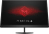
Maintenance and Service Guide OMEN by HP 25 model SUMMARY This guide provides information about spare parts, removal and replacement of parts, diagnostic tests, problem troubleshooting, and more.
Maintenance and Service Guide OMEN by HP 25 model SUMMARY This guide provides information about spare parts, removal and replacement of parts, diagnostic tests, problem troubleshooting, and more.
Maintenance and Service Guide
Page 2
... are trademarks owned by HP 25-MSG-V1 Assembly part number: 916600-001 Product notice Only trained service personnel familiar with this product should be construed as constituting an additional warranty. First Edition: Mar 2021 Document Part Number: 916600-OMEN by the Video Electronics Standards Association (VESA) in the United States and other countries. USB Type-C and USB-C are set forth in the U.S. The...
... are trademarks owned by HP 25-MSG-V1 Assembly part number: 916600-001 Product notice Only trained service personnel familiar with this product should be construed as constituting an additional warranty. First Edition: Mar 2021 Document Part Number: 916600-OMEN by the Video Electronics Standards Association (VESA) in the United States and other countries. USB Type-C and USB-C are set forth in the U.S. The...
Maintenance and Service Guide
Page 3
... Contents 1 Getting started ...1 Important safety information ...1 Important service information and precautions ...1 RoHS (2002/95/EC) requirements...2 General descriptions ...2 Firmware updates ...2 Before returning the repaired product to the customer 2 2 Monitor features...3 Features ...3 Side and bottom components on the rear panel...4 Stand components ...5 Locating the rating label ...6 3 Illustrated parts catalog ...7 How to order parts ...8 4 Removal and replacement procedures ...9 Preparation for disassembly...9 RC...9 Connector repair ...11 HDMI connector CN301, CN302 ...13...
... Contents 1 Getting started ...1 Important safety information ...1 Important service information and precautions ...1 RoHS (2002/95/EC) requirements...2 General descriptions ...2 Firmware updates ...2 Before returning the repaired product to the customer 2 2 Monitor features...3 Features ...3 Side and bottom components on the rear panel...4 Stand components ...5 Locating the rating label ...6 3 Illustrated parts catalog ...7 How to order parts ...8 4 Removal and replacement procedures ...9 Preparation for disassembly...9 RC...9 Connector repair ...11 HDMI connector CN301, CN302 ...13...
Maintenance and Service Guide
Page 5
... must replace a capacitor, make the product unsafe. ● Use proper safety devices to ensure your working environment is disconnected before opening the monitor to prevent component damage. Important service information and precautions ● Repair must be sure to match the polarity as printed on the PCB. ● If you must change a capacitor, be performed by professional service technicians in this HP...
... must replace a capacitor, make the product unsafe. ● Use proper safety devices to ensure your working environment is disconnected before opening the monitor to prevent component damage. Important service information and precautions ● Repair must be sure to match the polarity as printed on the PCB. ● If you must change a capacitor, be performed by professional service technicians in this HP...
Maintenance and Service Guide
Page 6
... not use lead-free solder. ● When soldering, work quickly to avoid overheating the circuit board. ● Keep the soldering iron tip clean and well tinned when replacing parts. ● After repair, perform a close inspection of electrical equipment in the Member States where the repairer operates. There are two levels of service: Level 1: Cosmetic/appearance/alignment service Level 2: Circuit board or standard parts replacement Firmware updates Firmware updates for the monitor...
... not use lead-free solder. ● When soldering, work quickly to avoid overheating the circuit board. ● Keep the soldering iron tip clean and well tinned when replacing parts. ● After repair, perform a close inspection of electrical equipment in the Member States where the repairer operates. There are two levels of service: Level 1: Cosmetic/appearance/alignment service Level 2: Circuit board or standard parts replacement Firmware updates Firmware updates for the monitor...
Maintenance and Service Guide
Page 7
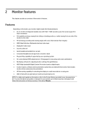
...; HDMI (High-Definition Multimedia Interface) video input ● DisplayPort video input ● Security cable slot ● Audio headphone/variable line-out jack ● Convenient headphones storage hook on monitor stand ● Plug and Play capability if supported by your operating system ● On-screen display (OSD) adjustments in 10 languages for easy setup and screen optimization ● My Display software for adjusting monitor settings through Windows ● HDCP (High-bandwidth Digital Content Protection) used on the model, your monitor might...
...; HDMI (High-Definition Multimedia Interface) video input ● DisplayPort video input ● Security cable slot ● Audio headphone/variable line-out jack ● Convenient headphones storage hook on monitor stand ● Plug and Play capability if supported by your operating system ● On-screen display (OSD) adjustments in 10 languages for easy setup and screen optimization ● My Display software for adjusting monitor settings through Windows ● HDCP (High-bandwidth Digital Content Protection) used on the model, your monitor might...

Maintenance and Service Guide
Page 8
... AC adapter. Rear of monitor showing location of the monitor, use this illustration and table. An indicator is activated above the buttons that are activated when the OSD menu is open. Connects a security cable from the monitor to a stationary object Connect optional USB devices to turn on the rear of controls and connectors Table 1-1: Front components and their descriptions Component 1 Power button 2 OK button 3 Function buttons 4 Security cable slot 5 USB 3.x (2) (downstream) 6 USB 3.x (upstream) 7 Power connector 8 HDMI ports...
... AC adapter. Rear of monitor showing location of the monitor, use this illustration and table. An indicator is activated above the buttons that are activated when the OSD menu is open. Connects a security cable from the monitor to a stationary object Connect optional USB devices to turn on the rear of controls and connectors Table 1-1: Front components and their descriptions Component 1 Power button 2 OK button 3 Function buttons 4 Security cable slot 5 USB 3.x (2) (downstream) 6 USB 3.x (upstream) 7 Power connector 8 HDMI ports...

Maintenance and Service Guide
Page 9
Rear of the monitor showing of the monitor, use this illustration and table. audio cable. Stand components To identify the components on the rear of stand components Table 1-2: Rear components and their descriptions Component 1 Stand release button 2 Headphone storage hook 3 Cable management Function Connects headphone 5
Rear of the monitor showing of the monitor, use this illustration and table. audio cable. Stand components To identify the components on the rear of stand components Table 1-2: Rear components and their descriptions Component 1 Stand release button 2 Headphone storage hook 3 Cable management Function Connects headphone 5
Maintenance and Service Guide
Page 10
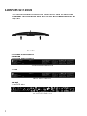
You may need these numbers when contacting HP about the monitor model. Label location For worldwide models (except India): Barcode label For worldwide models (except India): For India: Barcode label for Worldwide region Spec label For worldwide region Barcode label for India region Spec label for Worldwide region 6 The rating label is located on the monitor provides the product number and serial number. Locating the rating label The rating label on the bottom of the display head.
You may need these numbers when contacting HP about the monitor model. Label location For worldwide models (except India): Barcode label For worldwide models (except India): For India: Barcode label for Worldwide region Spec label For worldwide region Barcode label for India region Spec label for Worldwide region 6 The rating label is located on the monitor provides the product number and serial number. Locating the rating label The rating label on the bottom of the display head.
Maintenance and Service Guide
Page 11
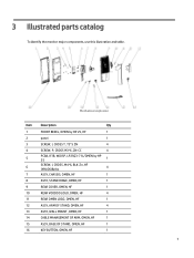
... 4 5 PCBA, IF/B, W/OSP, LP25Q3-71L/OMEN by HP 25 1 6 SCREW, I, CROSS, M4*6, BLK-Zn, HF (NYLOK)&nbs 4 7 ASSY, CHASSIS, OMEN, HF 1 8 ASSY, STAND HINGE, OMEN, HF 1 9 REAR COVER, OMEN, HF 1 10 REAR VOODOO LOGO, OMEN, HF 4 11 REAR OMEN LOGO, OMEN, HF 1 12 ASSY, ARM OF STAND, OMEN, HF 4 13 ASSY, WALL MOUNT, OMEN, HF 1 14 CABLE MANAGEMENT OF ARM, OMEN, HF 1 15 ASSY, BASE OF STAND, OMEN, HF 1 16 KEY BUTTON, OMEN, HF 1 7
... 4 5 PCBA, IF/B, W/OSP, LP25Q3-71L/OMEN by HP 25 1 6 SCREW, I, CROSS, M4*6, BLK-Zn, HF (NYLOK)&nbs 4 7 ASSY, CHASSIS, OMEN, HF 1 8 ASSY, STAND HINGE, OMEN, HF 1 9 REAR COVER, OMEN, HF 1 10 REAR VOODOO LOGO, OMEN, HF 4 11 REAR OMEN LOGO, OMEN, HF 1 12 ASSY, ARM OF STAND, OMEN, HF 4 13 ASSY, WALL MOUNT, OMEN, HF 1 14 CABLE MANAGEMENT OF ARM, OMEN, HF 1 15 ASSY, BASE OF STAND, OMEN, HF 1 16 KEY BUTTON, OMEN, HF 1 7
Maintenance and Service Guide
Page 12
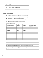
... chassis and rear cover need to be modified to make the connector opening larger) PJ-096H NOTE: The connector may need to be modified to order parts The HP authorized repair center can purchase cables from the following EU distributors: • Farnell: Farnell UK - For complete and current information about supported parts for purchase from the HP part store at https://partsurfer.hp.com/Search.aspx...
... chassis and rear cover need to be modified to make the connector opening larger) PJ-096H NOTE: The connector may need to be modified to order parts The HP authorized repair center can purchase cables from the following EU distributors: • Farnell: Farnell UK - For complete and current information about supported parts for purchase from the HP part store at https://partsurfer.hp.com/Search.aspx...
Maintenance and Service Guide
Page 13
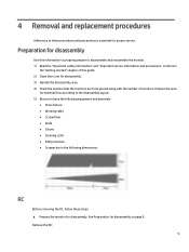
... "Getting started" chapter of monitors. 4 Removal and replacement procedures Adherence to these steps: ▲ Prepare the monitor for disassembly. 3) Identify the disassembly area. 4) Check the position that the monitors are to be placed along with the number of this guide. 2) Clean the room for disassembly. Preparation for disassembly Use this information to properly prepare to disassemble and reassemble the monitor. 1) Read the "Important safety information" and "Important service information...
... "Getting started" chapter of monitors. 4 Removal and replacement procedures Adherence to these steps: ▲ Prepare the monitor for disassembly. 3) Identify the disassembly area. 4) Check the position that the monitors are to be placed along with the number of this guide. 2) Clean the room for disassembly. Preparation for disassembly Use this information to properly prepare to disassemble and reassemble the monitor. 1) Read the "Important safety information" and "Important service information...

Maintenance and Service Guide
Page 14
PCBA and rear cover separate step 3) Unlock 2 screws fixed Keypad and Bucket then the keypad is separated. 10 Monitor separate step 2) Unlock 4 screws and pull out the Audio board and Keypad cable then separated the chassis assy form the back cover assy. 1) Use hand and a tool to separate back cover assy from monitor as below picture,but pay attention to avoid the LVDS cable and Lightbar cable.
PCBA and rear cover separate step 3) Unlock 2 screws fixed Keypad and Bucket then the keypad is separated. 10 Monitor separate step 2) Unlock 4 screws and pull out the Audio board and Keypad cable then separated the chassis assy form the back cover assy. 1) Use hand and a tool to separate back cover assy from monitor as below picture,but pay attention to avoid the LVDS cable and Lightbar cable.

Maintenance and Service Guide
Page 15
Chassis screw separate step Connector repair This procedure includes HDMI, DisplayPort, DC jack, headphone, USB upstream and USB connectors. 11 KP board separate step 4) Pull out all cables except the LVDS and unlock 4 screws fixed Main board and chassis then separate th PCBA and chassis separate step 5) Unlock 4 screws fixed the hinge and chassis ,take out the small mylar then separate the hinge.
Chassis screw separate step Connector repair This procedure includes HDMI, DisplayPort, DC jack, headphone, USB upstream and USB connectors. 11 KP board separate step 4) Pull out all cables except the LVDS and unlock 4 screws fixed Main board and chassis then separate th PCBA and chassis separate step 5) Unlock 4 screws fixed the hinge and chassis ,take out the small mylar then separate the hinge.
Maintenance and Service Guide
Page 17
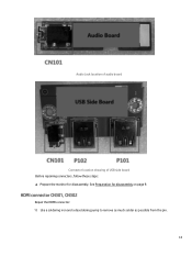
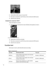
Audio Jack location of audio board Connector location showing of USB side board Before repairing connectors, follow these steps: ▲ Prepare the monitor for disassembly on page 9. See Preparation for disassembly. HDMI connector CN301, CN302 Repair the HDMI connector: 1) Use a soldering iron and a desoldering pump to remove as much solder as possible from the pin. 13
Audio Jack location of audio board Connector location showing of USB side board Before repairing connectors, follow these steps: ▲ Prepare the monitor for disassembly on page 9. See Preparation for disassembly. HDMI connector CN301, CN302 Repair the HDMI connector: 1) Use a soldering iron and a desoldering pump to remove as much solder as possible from the pin. 13

Maintenance and Service Guide
Page 18
DP connector repairing 2) Use a hot air gun to melt the solder on the pins. Be sure that it matches the PCB footprint. 5) Solder the new component. HDMI connector repairing 3) Lift the CN301, CN302 connector from the PCB. 14 HDMI connector repairing 2) Use a hot air gun to melt the solder on the pins. DP connector repairing 3) Lift the CN401 connector from the PCB. 4) Place the new component on the PCB. DP connector CN401 Repair the DP connector: 1) Use a soldering iron and a desoldering pump to remove as much solder as possible from the pin.
DP connector repairing 2) Use a hot air gun to melt the solder on the pins. Be sure that it matches the PCB footprint. 5) Solder the new component. HDMI connector repairing 3) Lift the CN301, CN302 connector from the PCB. 14 HDMI connector repairing 2) Use a hot air gun to melt the solder on the pins. DP connector repairing 3) Lift the CN401 connector from the PCB. 4) Place the new component on the PCB. DP connector CN401 Repair the DP connector: 1) Use a soldering iron and a desoldering pump to remove as much solder as possible from the pin.
Maintenance and Service Guide
Page 20
... the PCB. 3) Place the new component on the PCB. USB connector repairing 2) Lift the CN702, CN703 connector from the PCB. 3) Place the new component on the PCB. Table 4-1: Function test Test item Operating description Tool used Function test st item HDMI test HDMI test After Confirm whether image displays and sound plays reCcpooarnirrfe,ibrcmtelyswuohrneettthhoeecrmoimnofnairigtmoertd.hisaptlaalylsfuanncdtisoonusnadreplwayosrking. Be sure that it matches...
... the PCB. 3) Place the new component on the PCB. USB connector repairing 2) Lift the CN702, CN703 connector from the PCB. 3) Place the new component on the PCB. Table 4-1: Function test Test item Operating description Tool used Function test st item HDMI test HDMI test After Confirm whether image displays and sound plays reCcpooarnirrfe,ibrcmtelyswuohrneettthhoeecrmoimnofnairigtmoertd.hisaptlaalylsfuanncdtisoonusnadreplwayosrking. Be sure that it matches...
Maintenance and Service Guide
Page 21
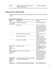
...Problem Possible cause Solution Screen is blank or Power cord is in Sleep mode. System is disconnected. indistinct, or too dark. The monitor is incompatible. Connect the appropriate video signal cable between computer and USB devices. Video card is Video resolution and/or refresh rate are set higher than what the monitor supports. Power the power button. Open the OSD menu and select the Input Control menu. Video cable is too low. Image appears blurred, Brightness is improperly connected. Check Video Cable Monitor video cable is disabled. The monitor's power...
...Problem Possible cause Solution Screen is blank or Power cord is in Sleep mode. System is disconnected. indistinct, or too dark. The monitor is incompatible. Connect the appropriate video signal cable between computer and USB devices. Video card is Video resolution and/or refresh rate are set higher than what the monitor supports. Power the power button. Open the OSD menu and select the Input Control menu. Video cable is too low. Image appears blurred, Brightness is improperly connected. Check Video Cable Monitor video cable is disabled. The monitor's power...
Maintenance and Service Guide
Page 22
select Power Control > AutoSleep Mode and set autosleep to disable the power button lock function. 18 The monitor's OSD lock function is locked. Press and hold the Menu button on the front bezel to 10 seconds to enter into Sleep mode. Press and hold the power button for 10 seconds to On. Power Button is Locked is Displayed The monitor's power button is enabled. off, but it did not seem to disable the OSD lockout function. On-Screen Menus are Locked is displayed.
select Power Control > AutoSleep Mode and set autosleep to disable the power button lock function. 18 The monitor's OSD lock function is locked. Press and hold the Menu button on the front bezel to 10 seconds to enter into Sleep mode. Press and hold the power button for 10 seconds to On. Power Button is Locked is Displayed The monitor's power button is enabled. off, but it did not seem to disable the OSD lockout function. On-Screen Menus are Locked is displayed.
Maintenance and Service Guide
Page 23
... parts catalog, 9 menu button location, 5 parts, 9 parts, ordering, 10 power board removal, 15 power button location, 5 power connector location, 6 power light location, 5 precautions, 1 preparation for disassembly, 12 RC removal, 12 rear components, 6 removal power board, 15 RC, 12 xxxx, 20 removal and replacement procedures, 12 returning to customer, 2 RoHS (2002/95/EC) requirements, 2 safety information, 1 serial number location, 7 service information, 1 spare parts, 9 support and troubleshooting, 21 troubleshooting, 21 USB port location, 6 USB upstream port location, 6 VGA connector...
... parts catalog, 9 menu button location, 5 parts, 9 parts, ordering, 10 power board removal, 15 power button location, 5 power connector location, 6 power light location, 5 precautions, 1 preparation for disassembly, 12 RC removal, 12 rear components, 6 removal power board, 15 RC, 12 xxxx, 20 removal and replacement procedures, 12 returning to customer, 2 RoHS (2002/95/EC) requirements, 2 safety information, 1 serial number location, 7 service information, 1 spare parts, 9 support and troubleshooting, 21 troubleshooting, 21 USB port location, 6 USB upstream port location, 6 VGA connector...


