Service Guide
Page 41
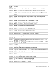
... battery 537617-001 Display assembly hinge covers 537618-001 Rubber Kit for use with black and blue models only (contains 4 device feet) 537618-002 Rubber Kit for use with pink, white, and HP Mini 110 by Studio Tord Boontje models only (contains 4 device feet) 537619-001 Heat sink assembly (includes replacement thermal material) 537620-001...
... battery 537617-001 Display assembly hinge covers 537618-001 Rubber Kit for use with black and blue models only (contains 4 device feet) 537618-002 Rubber Kit for use with pink, white, and HP Mini 110 by Studio Tord Boontje models only (contains 4 device feet) 537619-001 Heat sink assembly (includes replacement thermal material) 537620-001...
Service Guide
Page 42
...hinges) Webcam module System board (includes Intel Atom N270 1.6-GHz processor, 512-KB Level 2 cache, 533-MHz front-side bus (FSB), and thermal replacement material for use on the following model numbers only: HP: 110-1000 - 110-1099 and Compaq: 110c-1000 - 110-1099) 512-MB memory module (PC2-5300, 533-MHz, DDR2, for use in HP Mini 110... and Compaq: Mini 110 models only) 1024-MB ...
...hinges) Webcam module System board (includes Intel Atom N270 1.6-GHz processor, 512-KB Level 2 cache, 533-MHz front-side bus (FSB), and thermal replacement material for use on the following model numbers only: HP: 110-1000 - 110-1099 and Compaq: 110c-1000 - 110-1099) 512-MB memory module (PC2-5300, 533-MHz, DDR2, for use in HP Mini 110... and Compaq: Mini 110 models only) 1024-MB ...
Service Guide
Page 85
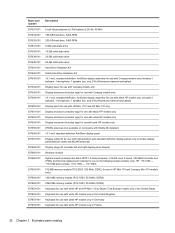
... AntiGlare display assembly (includes WWAN) ● 10.1-inch, WSVGA, AntiGlare display assembly (includes WWAN) For use with HP Mini 110 by Studio Tord Boontje models only ● 10.1-inch, high-definition, AntiGlare display assembly (includes WWAN) ● 10... WSVGA, AntiGlare display assembly (includes WWAN) Hinge covers Display bezel For use with HP Mini 1101 and HP Mini 110 only For use with HP Mini 110 by Studio Tord Boontje models only For use with Compaq Mini 110 only Spare part number 572407-001 572406-001...-001 537650-001 581324-001 537644-001 Component replacement procedures 75
... AntiGlare display assembly (includes WWAN) ● 10.1-inch, WSVGA, AntiGlare display assembly (includes WWAN) For use with HP Mini 110 by Studio Tord Boontje models only ● 10.1-inch, high-definition, AntiGlare display assembly (includes WWAN) ● 10... WSVGA, AntiGlare display assembly (includes WWAN) Hinge covers Display bezel For use with HP Mini 1101 and HP Mini 110 only For use with HP Mini 110 by Studio Tord Boontje models only For use with Compaq Mini 110 only Spare part number 572407-001 572406-001...-001 537650-001 581324-001 537644-001 Component replacement procedures 75

Service Guide
Page 86
... replacement procedures Shut down through the operating system. 2. Remove the battery (see Battery on , and then shut it down the device. Disconnect all external devices connected to the device. 3. Disconnect the power from the device by Studio Tord Boontje models only For use with HP Mini 110 ...by first unplugging the power cord from the AC outlet and then unplugging the AC adapter from the device. 4. Description Display Hinge Kit (Includes left and right display panel hinges) Speaker assembly (includes left and right cables)...
... replacement procedures Shut down through the operating system. 2. Remove the battery (see Battery on , and then shut it down the device. Disconnect all external devices connected to the device. 3. Disconnect the power from the device by Studio Tord Boontje models only For use with HP Mini 110 ...by first unplugging the power cord from the AC outlet and then unplugging the AC adapter from the device. 4. Description Display Hinge Kit (Includes left and right display panel hinges) Speaker assembly (includes left and right cables)...
Service Guide
Page 87
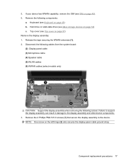
...the display assembly: 1. Failure to support the display assembly can result in damage to the device. NOTE: One screw on page 45). 6. Component replacement procedures 77 Disconnect the following cables from the system board: (2) Display panel cable (3) Microphone cable (4) Speaker cable (5) WLAN cables (6) WWAN cables ...capability, remove the SIM (see Mass storage devices on page 48) b. Hard drive or solid-state drive (see SIM on the left hinge (2) also secures the display panel cable ground strap. Remove the 4 Phillips PM2.5×5.0 screws (1) that secure the display assembly to ...
...the display assembly: 1. Failure to support the display assembly can result in damage to the device. NOTE: One screw on page 45). 6. Component replacement procedures 77 Disconnect the following cables from the system board: (2) Display panel cable (3) Microphone cable (4) Speaker cable (5) WLAN cables (6) WWAN cables ...capability, remove the SIM (see Mass storage devices on page 48) b. Hard drive or solid-state drive (see SIM on the left hinge (2) also secures the display panel cable ground strap. Remove the 4 Phillips PM2.5×5.0 screws (1) that secure the display assembly to ...

Service Guide
Page 88
Remove the display assembly (3). 5. b. If it is necessary to replace the display bezel, perform the following steps: a. Remove the display bezel (4). 78 Chapter 4 Removal and replacement procedures Flex the inside edges of the top and bottom (2), and then the left and right sides (3) of the display bezel until the bezel disengages from the display enclosure. c. Remove the display hinge covers (1). 4.
Remove the display assembly (3). 5. b. If it is necessary to replace the display bezel, perform the following steps: a. Remove the display bezel (4). 78 Chapter 4 Removal and replacement procedures Flex the inside edges of the top and bottom (2), and then the left and right sides (3) of the display bezel until the bezel disengages from the display enclosure. c. Remove the display hinge covers (1). 4.
Service Guide
Page 90
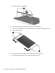
Remove the 2 Phillips PM2.0×3.0 screws (1) that secure each hinge to replace the display hinges, perform the following steps: a. If it is necessary to replace the display panel cable, perform the following steps: a. Remove the speaker assembly (2). 8. Remove the hinges (2). 9. b. b. Peel back the Mylar protection on the back of the display panel (1). 80 Chapter 4 Removal and replacement procedures If it is necessary to the display enclosure.
Remove the 2 Phillips PM2.0×3.0 screws (1) that secure each hinge to replace the display hinges, perform the following steps: a. If it is necessary to replace the display panel cable, perform the following steps: a. Remove the speaker assembly (2). 8. Remove the hinges (2). 9. b. b. Peel back the Mylar protection on the back of the display panel (1). 80 Chapter 4 Removal and replacement procedures If it is necessary to the display enclosure.


