HP PCL/PJL reference - Printer Job Language Technical Reference Addendum
Page 138
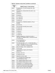
...58 SERVICE or FAN MOTOR FAILURE, CALL SERVICE 59 ERROR 60 ERROR 61.x SERVICE 62.x SERVICE 63 SERVICE 64 SERVICE or PRINTER ERROR, CYCLE POWER 40065 40066 40067 40068 40069 40070 40071 65 SERVICE External paper-handling device failure 67 SERVICE 69 SERVICE 70 ERROR 71 ERROR 72 SERVICE 40079...) 40089 40089 40090 40091 40092 40093 40096 40099 40100 40101 40102 40103 40104 BAD OPTIONAL TRAY CONNECTION For ELK BN INCOMPATIBLE ENVELOPE FEEDER INSTALLED Duplexer cord error 81 SERVICE (XXX) REMOVE DUPLEX JAM 41.3 UNEXPECTED PAPER SIZE CHECK PAPER IN TRAY 56.1 ERROR PRESS SELECT KEY 56.2 ERROR PRESS...
...58 SERVICE or FAN MOTOR FAILURE, CALL SERVICE 59 ERROR 60 ERROR 61.x SERVICE 62.x SERVICE 63 SERVICE 64 SERVICE or PRINTER ERROR, CYCLE POWER 40065 40066 40067 40068 40069 40070 40071 65 SERVICE External paper-handling device failure 67 SERVICE 69 SERVICE 70 ERROR 71 ERROR 72 SERVICE 40079...) 40089 40089 40090 40091 40092 40093 40096 40099 40100 40101 40102 40103 40104 BAD OPTIONAL TRAY CONNECTION For ELK BN INCOMPATIBLE ENVELOPE FEEDER INSTALLED Duplexer cord error 81 SERVICE (XXX) REMOVE DUPLEX JAM 41.3 UNEXPECTED PAPER SIZE CHECK PAPER IN TRAY 56.1 ERROR PRESS SELECT KEY 56.2 ERROR PRESS...

Service Manual
Page 40
If no response, check the power cord. both remain on Press and release the Control Panel Button to print. See "Service and error messages" in progress. On Blinking The printer is ready ...
If no response, check the power cord. both remain on Press and release the Control Panel Button to print. See "Service and error messages" in progress. On Blinking The printer is ready ...

Service Manual
Page 58
...located on DC Controller PCA) The AC, DC, and high voltage power supply circuits are all of black vertical lines. AC power distribution The AC power circuitry supplies AC voltage whenever the power cord is distributed to the DC power supply circuitry and to the fusing assembly's heating element. 56 Functional...paper movement. The Motor provides all contained within the DC Controller PCA. AC voltage is connected to drive the Laser/Scanner motor. Power system (on the top of the printer. The front door must be closed before the printer can resume printing. Paper motion monitoring...
...located on DC Controller PCA) The AC, DC, and high voltage power supply circuits are all of black vertical lines. AC power distribution The AC power circuitry supplies AC voltage whenever the power cord is distributed to the DC power supply circuitry and to the fusing assembly's heating element. 56 Functional...paper movement. The Motor provides all contained within the DC Controller PCA. AC voltage is connected to drive the Laser/Scanner motor. Power system (on the top of the printer. The front door must be closed before the printer can resume printing. Paper motion monitoring...

Service Manual
Page 72
... the power cord from the Laser/Scanner Assembly. CAUTION The printer contains parts that are included to align it counter-clockwise to provide direction for difficult or critical replacement procedures. Never operate or service the printer with the existing thread pattern, then carefully turn it with the protective cover removed from the power...
... the power cord from the Laser/Scanner Assembly. CAUTION The printer contains parts that are included to align it counter-clockwise to provide direction for difficult or critical replacement procedures. Never operate or service the printer with the existing thread pattern, then carefully turn it with the protective cover removed from the power...

Service Manual
Page 74
... Memory Expansion Cover by carefully pulling the tab out and away from light while you have added. Print a self-test page (see Chapter 3) to the power source. Your Total Memory in SleepMode. 2 2 Open the Printer Door, remove the toner cartridge, and close the Printer Door. You should not install a memory card... side so that the printer recognizes the additional memory you are working on top as in the paper tray. Installing memory cards (DRAM) 1 Note The HP LaserJet 6L Pro does not support memory upgrades. 1 Unplug the power cord from the printer.
... Memory Expansion Cover by carefully pulling the tab out and away from light while you have added. Print a self-test page (see Chapter 3) to the power source. Your Total Memory in SleepMode. 2 2 Open the Printer Door, remove the toner cartridge, and close the Printer Door. You should not install a memory card... side so that the printer recognizes the additional memory you are working on top as in the paper tray. Installing memory cards (DRAM) 1 Note The HP LaserJet 6L Pro does not support memory upgrades. 1 Unplug the power cord from the printer.

Service Manual
Page 75
It does not have removed the covers, leave the Input Extender in the photo. The Input Extender for the HP LaserJet 6L Pro differs from the back of the printer. 2 Remove the toner cartridge. 3 Lift the Input Extender assembly. After you have the extra extender for... replacement. You must lift the Input Extender when the covers are removed or it will break. Covers and doors CAUTION Note Back Cover 1 Unplug the power cord and remove the parallel cable from the one shown in this lifted position for legal-size paper. 4 Remove the (3) screws (Figure 6-2, callout 1). 1 Figure 6-2 Back ...
It does not have removed the covers, leave the Input Extender in the photo. The Input Extender for the HP LaserJet 6L Pro differs from the back of the printer. 2 Remove the toner cartridge. 3 Lift the Input Extender assembly. After you have the extra extender for... replacement. You must lift the Input Extender when the covers are removed or it will break. Covers and doors CAUTION Note Back Cover 1 Unplug the power cord and remove the parallel cable from the one shown in this lifted position for legal-size paper. 4 Remove the (3) screws (Figure 6-2, callout 1). 1 Figure 6-2 Back ...

Service Manual
Page 77
Figure 6-4 EP Door Assembly removal EN Covers and doors 75 The right tab will fall out easily. EP Door Assembly 1 Unplug the power cord and remove the parallel cable from the back of the printer. 2 Open the EP Door. 3 Remove the toner cartridge. 4 There is a flex point along the door hinge. Firmly press the left tab inward to release it (Figure 6- 4).
Figure 6-4 EP Door Assembly removal EN Covers and doors 75 The right tab will fall out easily. EP Door Assembly 1 Unplug the power cord and remove the parallel cable from the back of the printer. 2 Open the EP Door. 3 Remove the toner cartridge. 4 There is a flex point along the door hinge. Firmly press the left tab inward to release it (Figure 6- 4).

Service Manual
Page 78
Note Memory Door This procedure does not apply to the HP LaserJet 6L Pro. That model does not have a Memory Door. 1 Unplug the power cord and remove the parallel cable from the back of the printer. 2 Remove the toner cartridge. 3 Gently tip the printer onto its side so that the Control Panel is on top. 4 Carefully pull the door tab out (Figure 6-5, callout 1) and away from the printer in a gentle rocking motion (Figure 6-5, callout 2). 2 1 Figure 6-5 Memory Door removal 76 Removal and replacement EN
Note Memory Door This procedure does not apply to the HP LaserJet 6L Pro. That model does not have a Memory Door. 1 Unplug the power cord and remove the parallel cable from the back of the printer. 2 Remove the toner cartridge. 3 Gently tip the printer onto its side so that the Control Panel is on top. 4 Carefully pull the door tab out (Figure 6-5, callout 1) and away from the printer in a gentle rocking motion (Figure 6-5, callout 2). 2 1 Figure 6-5 Memory Door removal 76 Removal and replacement EN

Service Manual
Page 118
... not functional: 1 Verify that the Control Panel connector J9 is seated into both the Control Panel and the Formatter PCA at the input power receptacle and that the power cord is firmly inserted into the printer. 2 Verify that FU102 is not open. (See Figure 7-2.) 3 Verify that the motor is correctly mounted to the...
... not functional: 1 Verify that the Control Panel connector J9 is seated into both the Control Panel and the Formatter PCA at the input power receptacle and that the power cord is firmly inserted into the printer. 2 Verify that FU102 is not open. (See Figure 7-2.) 3 Verify that the motor is correctly mounted to the...

Service Manual
Page 124
.... Verify that all connectors are correctly seated, yet the error persists, replace the DC Controller PCA. 122 Troubleshooting EN Check power cord connections and the power source. 3. The printer is functional. If this chapter. Verify that all three photosensor flags are not functional. 1. If... the Fusing Assembly. (Refer to the printer. This flag is functioning. (See "Printing an Engine Test" later in Sleep Mode. Power is not supplied to Figure 6-18.) If all of 2) LEDs Description Recommended action Sleep Mode. Note Table 7-1 Printer status messages (...
.... Verify that all connectors are correctly seated, yet the error persists, replace the DC Controller PCA. 122 Troubleshooting EN Check power cord connections and the power source. 3. The printer is functional. If this chapter. Verify that all three photosensor flags are not functional. 1. If... the Fusing Assembly. (Refer to the printer. This flag is functioning. (See "Printing an Engine Test" later in Sleep Mode. Power is not supplied to Figure 6-18.) If all of 2) LEDs Description Recommended action Sleep Mode. Note Table 7-1 Printer status messages (...

Service Manual
Page 188
... rotation 116 overcurrent/overvoltage protection 57 rating information 15 shutoff switch 56 specifications 18 testing high voltage power supply 135 troubleshooting 116 power cable connector, locating 21 power cord, unplugging 70 power receptacle 119 power supplies, uninterruptible (UPS) 32, 123 power-on 144 photosensitive drum. Americas (CSSO-A) 144 Commercial Service and Support Organization-Europe (CSSO-E) 144 ordering...
... rotation 116 overcurrent/overvoltage protection 57 rating information 15 shutoff switch 56 specifications 18 testing high voltage power supply 135 troubleshooting 116 power cable connector, locating 21 power cord, unplugging 70 power receptacle 119 power supplies, uninterruptible (UPS) 32, 123 power-on 144 photosensitive drum. Americas (CSSO-A) 144 Commercial Service and Support Organization-Europe (CSSO-E) 144 ordering...

