HP PCL/PJL reference - Printer Job Language Technical Reference Addendum
Page 137
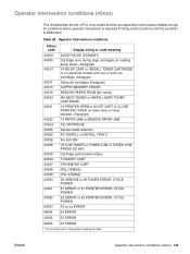
... sheet-Designjet) 14 NO EP CART or INSTALL TONER CARTRIDGE or no electrical contact with one or more ink cartridges (Designjet) Using ink cartridges (Designjet) SUPPLY MEMORY ERROR REMOVE PAPER FROM [bin name] NO MICR TONER or INSTALL MICR TONER CARTRIDGE 12 PRINTER OPEN or NO EP CART or CLOSE PRINTER... status FI INSERT CART FR REMOVE CART [PJL OPMSG] [PJL STMSG] 50 SERVICE or 50 FUSER ERROR, CYCLE POWER 51 ERROR or 51 PRINTER ERROR, CYCLE POWER 52 ERROR or 52 PRINTER ERROR, CYCLE POWER 53-xy-zz ERROR 40054 54 ERROR 40055 55 ERROR 40056 56 ERROR * This is addressed. The printer...
... sheet-Designjet) 14 NO EP CART or INSTALL TONER CARTRIDGE or no electrical contact with one or more ink cartridges (Designjet) Using ink cartridges (Designjet) SUPPLY MEMORY ERROR REMOVE PAPER FROM [bin name] NO MICR TONER or INSTALL MICR TONER CARTRIDGE 12 PRINTER OPEN or NO EP CART or CLOSE PRINTER... status FI INSERT CART FR REMOVE CART [PJL OPMSG] [PJL STMSG] 50 SERVICE or 50 FUSER ERROR, CYCLE POWER 51 ERROR or 51 PRINTER ERROR, CYCLE POWER 52 ERROR or 52 PRINTER ERROR, CYCLE POWER 53-xy-zz ERROR 40054 54 ERROR 40055 55 ERROR 40056 56 ERROR * This is addressed. The printer...
HP PCL/PJL reference - Printer Job Language Technical Reference Manual
Page 61
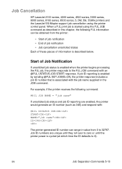
... unsolicited job status and job ID reporting are unique until they roll over to 32767. Job Cancellation HP LaserJet 2100 series, 4000 series, 4500 series, 5000 series, 8000 series, 8100 series, 8500 series, 5, 5M, 5Si, 5SiMx printers... and the LaserJet 5Si Mopier support job cancellation using the PJL JOB command as 346) and respond with an @PJL USTATUS...printer-generated ID number can be obtained from 0 to zero or until the printer power is associated with the job name supplied in the JOB command.
... unsolicited job status and job ID reporting are unique until they roll over to 32767. Job Cancellation HP LaserJet 2100 series, 4000 series, 4500 series, 5000 series, 8000 series, 8100 series, 8500 series, 5, 5M, 5Si, 5SiMx printers... and the LaserJet 5Si Mopier support job cancellation using the PJL JOB command as 346) and respond with an @PJL USTATUS...printer-generated ID number can be obtained from 0 to zero or until the printer power is associated with the job name supplied in the JOB command.

HP LaserJet 6L Printer - User Manual
Page 33
... does not respond after a 15-minute wait. The printer has malfunctioned. Check the power cord connections and power source. Refer to wake it with climates having high humidity). All the printer's lights...Add only one transparency or 20 sheets of other media to stack up to your HP authorized service representative. If printing more than one sheet at a time into an upside.... You may effectively decrease multi-feeds. To order, see appendix A, "Accessories and Supplies Information." Do not allow more than 7 envelopes for areas with a 1-, 2-, 4-, or 8-MB, 70ns or...
... does not respond after a 15-minute wait. The printer has malfunctioned. Check the power cord connections and power source. Refer to wake it with climates having high humidity). All the printer's lights...Add only one transparency or 20 sheets of other media to stack up to your HP authorized service representative. If printing more than one sheet at a time into an upside.... You may effectively decrease multi-feeds. To order, see appendix A, "Accessories and Supplies Information." Do not allow more than 7 envelopes for areas with a 1-, 2-, 4-, or 8-MB, 70ns or...
HP LaserJet 6L Printer - User Manual
Page 61
...15 noise level B-1 O online help How Do I 1-9 overview 1-9 status window 1-9 troubleshooting 1-9 using 1-9 operating environment B-1 ordering accessories A-3 information A-3 supplies A-3 output paper path 3-2 ozone emission B-4 P paper adding 1-5, 3-2 centering 1-5 custom-sized 3-1 loading 1-5 ordering A-3 orientation 3-1 realigning 1-5 recycled ... 1-8 photosensitive drum 4-8 Poland, sales and service A-7 postcards, output options 3-2 power consumption B-1 power requirements B-1 preparing for printing 3-1 print density, adjusting 4-9 print job, deleting 3-6 print media 3-1 SEE envelopes...
...15 noise level B-1 O online help How Do I 1-9 overview 1-9 status window 1-9 troubleshooting 1-9 using 1-9 operating environment B-1 ordering accessories A-3 information A-3 supplies A-3 output paper path 3-2 ozone emission B-4 P paper adding 1-5, 3-2 centering 1-5 custom-sized 3-1 loading 1-5 ordering A-3 orientation 3-1 realigning 1-5 recycled ... 1-8 photosensitive drum 4-8 Poland, sales and service A-7 postcards, output options 3-2 power consumption B-1 power requirements B-1 preparing for printing 3-1 print density, adjusting 4-9 print job, deleting 3-6 print media 3-1 SEE envelopes...

Service Manual
Page 3
Publication number C3990-90991 First edition, May 1997 Warranty The information contained in connection with the furnishing, performance, or use only supplied power cords and connect only to this material. Hewlett-Packard shall not be liable for errors contained herein or for a particular purpose. WARNING Electrical Shock Hazard ...
Publication number C3990-90991 First edition, May 1997 Warranty The information contained in connection with the furnishing, performance, or use only supplied power cords and connect only to this material. Hewlett-Packard shall not be liable for errors contained herein or for a particular purpose. WARNING Electrical Shock Hazard ...

Service Manual
Page 8
... (1 of 3 7-10 Service and Error Messages (Continued 2 of 3 7-11 Service and Error Messages (Continued 3 of 3 7-12 High-Voltage Power Supply Check 7-24 Paper Curl Troubleshooting 7-26 Cable Pinouts 7-30 Cable Pinouts 7-31 Accessories and Supplies 8-5 Common Fasteners Used in the Printer 8-6 Covers and Doors 8-9 Internal Components (1 of 3 8-11 Internal Components (2 of 3 8-13 Internal...
... (1 of 3 7-10 Service and Error Messages (Continued 2 of 3 7-11 Service and Error Messages (Continued 3 of 3 7-12 High-Voltage Power Supply Check 7-24 Paper Curl Troubleshooting 7-26 Cable Pinouts 7-30 Cable Pinouts 7-31 Accessories and Supplies 8-5 Common Fasteners Used in the Printer 8-6 Covers and Doors 8-9 Internal Components (1 of 3 8-11 Internal Components (2 of 3 8-13 Internal...

Service Manual
Page 28
...power supplies (UPS) should not be maintained to block any direct sunlight. • Install with enough space around the printer for proper access and ventilation. (See Figure 2-1.) • Install printer away from the direct flow of this printer. • Install away from direct sunlight, open flames, or ammonia fumes. Environmental Requirements LaserJet 5L/6L...in a well-ventilated, dust-free area. • Install on carpet or other soft surfaces. • Ensure adequate power is placed near a window, make sure the window has a curtain or blind to ensure the proper operation of ...
...power supplies (UPS) should not be maintained to block any direct sunlight. • Install with enough space around the printer for proper access and ventilation. (See Figure 2-1.) • Install printer away from the direct flow of this printer. • Install away from direct sunlight, open flames, or ammonia fumes. Environmental Requirements LaserJet 5L/6L...in a well-ventilated, dust-free area. • Install on carpet or other soft surfaces. • Ensure adequate power is placed near a window, make sure the window has a curtain or blind to ensure the proper operation of ...

Service Manual
Page 55
... Figure 5-2 shows the various DC controller loads. AC Driver Low-Voltage +5V Supply +12V DC Controller Loads 5 - 4 Functional Overview The DC Controller also includes both AC and DC power supply and distribution circuitry. Figure 5-2 DC Controller/Power System The DC Controller PCA coordinates all print engine activities, drives the laser, and coordinates print data...
... Figure 5-2 shows the various DC controller loads. AC Driver Low-Voltage +5V Supply +12V DC Controller Loads 5 - 4 Functional Overview The DC Controller also includes both AC and DC power supply and distribution circuitry. Figure 5-2 DC Controller/Power System The DC Controller PCA coordinates all print engine activities, drives the laser, and coordinates print data...

Service Manual
Page 57
.... After the printer has been idle for the fusing system circuitry. AC Power Distribution The AC power circuitry supplies AC voltage whenever the power cord is distributed to the DC power supply circuitry and to the AC driver circuitry, which automatically shuts off by shifting...Formatter PCA Photosensors DC Controller Circuitry Laser/Beam Detect Circuitry +12 V DC: +12VA DC: Motor Scanner Motor Solenoid High Voltage Power Supply Overcurrent/Overvoltage Protection There are all printer settings and downloaded fonts and macros while in this printer: • Fuse F101 provides ...
.... After the printer has been idle for the fusing system circuitry. AC Power Distribution The AC power circuitry supplies AC voltage whenever the power cord is distributed to the DC power supply circuitry and to the AC driver circuitry, which automatically shuts off by shifting...Formatter PCA Photosensors DC Controller Circuitry Laser/Beam Detect Circuitry +12 V DC: +12VA DC: Motor Scanner Motor Solenoid High Voltage Power Supply Overcurrent/Overvoltage Protection There are all printer settings and downloaded fonts and macros while in this printer: • Fuse F101 provides ...

Service Manual
Page 58
Note The printer exits SleepMode and all of the lights power on the DC Controller PCA. This circuit also controls the image density by changing the primary AC voltage and the developing AC bias according to ... according to the primary charging roller and the developing roller. High voltage is disabled when the printer's EP Door is open ). High Voltage Power Distribution The High Voltage Power Supply PCA applies an overlap of DC and AC voltage to the instructions from the CPU on when any of the print density dial...
Note The printer exits SleepMode and all of the lights power on the DC Controller PCA. This circuit also controls the image density by changing the primary AC voltage and the developing AC bias according to ... according to the primary charging roller and the developing roller. High voltage is disabled when the printer's EP Door is open ). High Voltage Power Distribution The High Voltage Power Supply PCA applies an overlap of DC and AC voltage to the instructions from the CPU on when any of the print density dial...

Service Manual
Page 122
... Cartridge 7-13 Image Defect Examples 7-14 Troubleshooting Checks 7-21 Engine Test 7-21 Half-Self Test Functional Check 7-22 Drum Rotation Functional Check 7-23 High-Voltage Power Supply Check 7-24 Paper Curl 7-26 Troubleshooting Tools 7-27 Paper Path Check 7-27 Repetitive Image Defect Ruler 7-28 Main Wiring Diagram 7-29 Troubleshooting 7-1
... Cartridge 7-13 Image Defect Examples 7-14 Troubleshooting Checks 7-21 Engine Test 7-21 Half-Self Test Functional Check 7-22 Drum Rotation Functional Check 7-23 High-Voltage Power Supply Check 7-24 Paper Curl 7-26 Troubleshooting Tools 7-27 Paper Path Check 7-27 Repetitive Image Defect Ruler 7-28 Main Wiring Diagram 7-29 Troubleshooting 7-1

Service Manual
Page 130
...PS203) and/or their flags are not functional. 1. Press the Front Panel Button or open the EP Door. 2. If the test is not supplied to identify photosensor flag locations.) • Paper Out Flag (PS202) (See Figure 5-6.) • Paper Registration Flag (PS203) (See Figure 5-6.)...yet the error persists, replace the DC Controller PCA. Troubleshooting 7-9 Power is successful, replace the Formatter PCA. 4. Verify that the printer still displays an error message. Check power cord connections and the power source. 3. Occasionally you attempt to identify connector locations on the ...
...PS203) and/or their flags are not functional. 1. Press the Front Panel Button or open the EP Door. 2. If the test is not supplied to identify photosensor flag locations.) • Paper Out Flag (PS202) (See Figure 5-6.) • Paper Registration Flag (PS203) (See Figure 5-6.)...yet the error persists, replace the DC Controller PCA. Troubleshooting 7-9 Power is successful, replace the Formatter PCA. 4. Verify that the printer still displays an error message. Check power cord connections and the power source. 3. Occasionally you attempt to identify connector locations on the ...

Service Manual
Page 131
.... 4. Replace the Formatter PCA. Remove the connector from J102 of service error has occurred. This indicates a fusing assembly malfunction. Uninterruptible power supplies (UPS) should not be displayed as long as this doesn't clear the error: 2. Press and hold the Front Panel Button to ...feedback) connector (See Figure 7-3). Note: Chronic fuser failures or fuser overheating or both the printer chassis and J206 of an uninterruptible power supply or battery backup being used with the printer. Fuser Error. The printer believes that the fuser connector is firmly seated in . When...
.... 4. Replace the Formatter PCA. Remove the connector from J102 of service error has occurred. This indicates a fusing assembly malfunction. Uninterruptible power supplies (UPS) should not be displayed as long as this doesn't clear the error: 2. Press and hold the Front Panel Button to ...feedback) connector (See Figure 7-3). Note: Chronic fuser failures or fuser overheating or both the printer chassis and J206 of an uninterruptible power supply or battery backup being used with the printer. Fuser Error. The printer believes that the fuser connector is firmly seated in . When...

Service Manual
Page 143
... Functional Check The electrophotographic process can be subdivided into the following functional checks: 1 Make sure you installed the cartridge. 2 Drum Rotation Functional Check. 3 High Voltage Power Supply Check. 7-22 Troubleshooting If NO image is present on the drum's surface, assume that the first four functions of the paper should have removed the...
... Functional Check The electrophotographic process can be subdivided into the following functional checks: 1 Make sure you installed the cartridge. 2 Drum Rotation Functional Check. 3 High Voltage Power Supply Check. 7-22 Troubleshooting If NO image is present on the drum's surface, assume that the first four functions of the paper should have removed the...

Service Manual
Page 145
High-Voltage Power Supply Check Checks Toner Cartridge Connection Points High Voltage Connector Assembly Action Visually inspect the three connection points on the following page.) Verify that the pins .... Toner Cartridge High Voltage Connection Points (1 of the toner cartridge. Use alcohol only. If they are dirty, clean using alcohol only; Table 7-5 Figure 7-5 High-Voltage Power Supply Check The High-Voltage Power Supply PCA provides the necessary voltages for verifying the high-voltage system is functional. A method for the electrophotographic processes.
High-Voltage Power Supply Check Checks Toner Cartridge Connection Points High Voltage Connector Assembly Action Visually inspect the three connection points on the following page.) Verify that the pins .... Toner Cartridge High Voltage Connection Points (1 of the toner cartridge. Use alcohol only. If they are dirty, clean using alcohol only; Table 7-5 Figure 7-5 High-Voltage Power Supply Check The High-Voltage Power Supply PCA provides the necessary voltages for verifying the high-voltage system is functional. A method for the electrophotographic processes.

Service Manual
Page 200
... purpose 7-22 half self test functional check 7-22 hardware, common 8-6 high voltage power distribution 5-7 high voltage power supply PCA 5-7 high-voltage power supply check 7-24 horizontal stripes 7-15 HPD, HP's Distribution Center 1-11 I identification, labels 1-4 identification, printer 1-4 image defects 7-... 5-13 drum rotation functional check 7-23 E EconoMode 1-3, 5-10 print speed 5-10 vs. Index Index A AC power distribution 5-6 circuitry 5-6 accessories and supplies 8-5 acoustic emissions 1-6 assistance, technical 1-12 B background scatter 7-16 black page 7-16 blank page all pages 7-...
... purpose 7-22 half self test functional check 7-22 hardware, common 8-6 high voltage power distribution 5-7 high voltage power supply PCA 5-7 high-voltage power supply check 7-24 horizontal stripes 7-15 HPD, HP's Distribution Center 1-11 I identification, labels 1-4 identification, printer 1-4 image defects 7-... 5-13 drum rotation functional check 7-23 E EconoMode 1-3, 5-10 print speed 5-10 vs. Index Index A AC power distribution 5-6 circuitry 5-6 accessories and supplies 8-5 acoustic emissions 1-6 assistance, technical 1-12 B background scatter 7-16 black page 7-16 blank page all pages 7-...
Service Manual
Page 201
... assembly 8-18 PJL overview 5-11 PJL, Printer Display Language Centronics cabeling 5-11 described 5-11 print environment settings 5-11 two-way communication 5-11 power surge 1-15 power control 1-3 power distribution, AC 5-6 power save mode 1-3, 5-6 power supply system 5-4 preliminary troubleshooting 7-3 print environment settings, PJL 5-11 print quality cleaning printer 4-6 transfer roller 4-7 print quality problems 7-14 all blank pages...
... assembly 8-18 PJL overview 5-11 PJL, Printer Display Language Centronics cabeling 5-11 described 5-11 print environment settings 5-11 two-way communication 5-11 power surge 1-15 power control 1-3 power distribution, AC 5-6 power save mode 1-3, 5-6 power supply system 5-4 preliminary troubleshooting 7-3 print environment settings, PJL 5-11 print quality cleaning printer 4-6 transfer roller 4-7 print quality problems 7-14 all blank pages...

Service Manual
Page 202
... feed 7-8 memory error 7-8 paper jam 7-8 paper out 7-8 Ready 7-8 SleepMode 7-9 STBY, printer timing 5-19 supplies 8-5 See alsoaccessories and supplies surge protection 1-15 SW101, 12 volt dc power shutoff microswitch 5-5 SW101, printer door microswitch 5-5 SW201, engine test microswitch 5-5 T technical assistance 1-12 test, ...separation pad 6-37 solenoid 6-25 transfer roller 6-34 transferring process 5-14 troubleshooting 7-1 to 7-32 drum rotation 7-23 high-voltage power supply check 7-24 image defects 7-28 image formation 7-13 LEDs 7-7 paper curl 7-26 paper path 7-27 print quality problems 7-14...
... feed 7-8 memory error 7-8 paper jam 7-8 paper out 7-8 Ready 7-8 SleepMode 7-9 STBY, printer timing 5-19 supplies 8-5 See alsoaccessories and supplies surge protection 1-15 SW101, 12 volt dc power shutoff microswitch 5-5 SW101, printer door microswitch 5-5 SW201, engine test microswitch 5-5 T technical assistance 1-12 test, ...separation pad 6-37 solenoid 6-25 transfer roller 6-34 transferring process 5-14 troubleshooting 7-1 to 7-32 drum rotation 7-23 high-voltage power supply check 7-24 image defects 7-28 image formation 7-13 LEDs 7-7 paper curl 7-26 paper path 7-27 print quality problems 7-14...

