Service Manual
Page 6
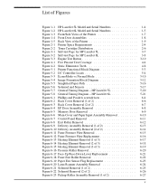
... 6-21 Solenoid Removal (1 of 2 6-25 Figure 6-22 Solenoid Removal (2 of 2 6-26 Figure 6-23 Pickup Roller Assembly Removal (1 of the Printer 1-9 Figure 2-1 Printer Space Requirements 2-4 Figure 2-2 Toner Cartridge Distribution 2-6 Figure 3-1 Self-test Page for HP LaserJet 5L 3-7 Figure 3-2 Self-test Page for HP LaserJet 6L 3-8 Figure 3-3 Engine Test Button 3-10 Figure 4-1 Five Percent Text Coverage 4-4 Figure 4-2 Static Eliminator...
... 6-21 Solenoid Removal (1 of 2 6-25 Figure 6-22 Solenoid Removal (2 of 2 6-26 Figure 6-23 Pickup Roller Assembly Removal (1 of the Printer 1-9 Figure 2-1 Printer Space Requirements 2-4 Figure 2-2 Toner Cartridge Distribution 2-6 Figure 3-1 Self-test Page for HP LaserJet 5L 3-7 Figure 3-2 Self-test Page for HP LaserJet 6L 3-8 Figure 3-3 Engine Test Button 3-10 Figure 4-1 Five Percent Text Coverage 4-4 Figure 4-2 Static Eliminator...
Service Manual
Page 7
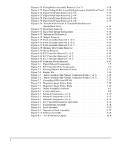
... and Doors 8-8 Figure 8-3 Internal Components (1 of 3 8-10 Figure 8-4 Internal Components (2 of 3 8-12 Figure 8-5 Internal Components (3 of 3 8-14 Figure 8-6 DC Controller/Formatter and Cables 8-16 Figure 8-7 Pickup Roller Assembly 8-18 Figure 8-8 Feed Assembly 8-20 Figure 8-9 Separation Guide Assembly 8-22 Figure 8-10 Delivery Assembly 8-24 Figure B-1 VCCI Statement (Japan B-4 vi
... and Doors 8-8 Figure 8-3 Internal Components (1 of 3 8-10 Figure 8-4 Internal Components (2 of 3 8-12 Figure 8-5 Internal Components (3 of 3 8-14 Figure 8-6 DC Controller/Formatter and Cables 8-16 Figure 8-7 Pickup Roller Assembly 8-18 Figure 8-8 Feed Assembly 8-20 Figure 8-9 Separation Guide Assembly 8-22 Figure 8-10 Delivery Assembly 8-24 Figure B-1 VCCI Statement (Japan B-4 vi

Service Manual
Page 50
Remove all dust, spilled toner, and paper particles. Contaminants on or around the printer. Do not touch the transfer roller with your fingers. (For location, see Figure 6-30.) Use a dry lint-free cloth. (For location, see Figure... Maintenance Printer Maintenance 4-7 Do not use ammonia-based cleaners on the roller can cause print quality problems. Cleaning Printer Components COMPONENT Outside Covers Inside General Exit Roller Fuser Exit Roller Pickup Roller Pressure Roller Transfer Roller Separation Pad Delivery Assembly Static Eliminator Teeth CLEANING METHOD/NOTES Use a water...
Remove all dust, spilled toner, and paper particles. Contaminants on or around the printer. Do not touch the transfer roller with your fingers. (For location, see Figure 6-30.) Use a dry lint-free cloth. (For location, see Figure... Maintenance Printer Maintenance 4-7 Do not use ammonia-based cleaners on the roller can cause print quality problems. Cleaning Printer Components COMPONENT Outside Covers Inside General Exit Roller Fuser Exit Roller Pickup Roller Pressure Roller Transfer Roller Separation Pad Delivery Assembly Static Eliminator Teeth CLEANING METHOD/NOTES Use a water...
Service Manual
Page 68
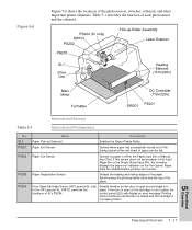
Figure 5-6 Figure 5-6 shows the locations of paper can resume. SL1 PS201 PS202 PS203 PS204 Name Description Paper Pick-up Solenoid Enables the Paper Pickup Roller. Paper Out Sensor Senses no paper in the Input Paper Bin or the Single-Sheet Input Slot, the formatter displays the paper-out indication on ... not sense paper in either the Paper Input Bin or Manual Input Slot. Solenoid and Sensors Table 5-1 Solenoid and Photosensors No. Door Open/Cartridge Sensor (HP LaserJet 5L only) In the HP LaserJet 6L, SW101 performs the functions of each photosensor and the solenoid.
Figure 5-6 Figure 5-6 shows the locations of paper can resume. SL1 PS201 PS202 PS203 PS204 Name Description Paper Pick-up Solenoid Enables the Paper Pickup Roller. Paper Out Sensor Senses no paper in the Input Paper Bin or the Single-Sheet Input Slot, the formatter displays the paper-out indication on ... not sense paper in either the Paper Input Bin or Manual Input Slot. Solenoid and Sensors Table 5-1 Solenoid and Photosensors No. Door Open/Cartridge Sensor (HP LaserJet 5L only) In the HP LaserJet 6L, SW101 performs the functions of each photosensor and the solenoid.
Service Manual
Page 74
... 6-22 Paper Exit Sensor Flag 6-23 Top Assemblies 6-24 Laser/Scanner Assembly 6-24 Solenoid 6-25 Pickup Roller Assembly 6-27 Paper Feed Frame 6-30 Transfer Roller Guide & Transfer Roller 6-34 Kick Plate 6-35 Separation Pad 6-37 Subpads 6-38 Feed Assembly 6-39 Bottom Assemblies 6-42 Memory Door Guide 6-42 Motor 6-43 DC Controller 6-44 Formatter ...
... 6-22 Paper Exit Sensor Flag 6-23 Top Assemblies 6-24 Laser/Scanner Assembly 6-24 Solenoid 6-25 Pickup Roller Assembly 6-27 Paper Feed Frame 6-30 Transfer Roller Guide & Transfer Roller 6-34 Kick Plate 6-35 Separation Pad 6-37 Subpads 6-38 Feed Assembly 6-39 Bottom Assemblies 6-42 Memory Door Guide 6-42 Motor 6-43 DC Controller 6-44 Formatter ...
Service Manual
Page 100
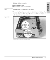
Pickup Roller Assembly Removal (1 of the clip up and over the two metal guides and sliding the clip off. This gear is shaped differently. The clip from an HP LaserJet 5L. Figure 6-23 depicts the clip from an HP LaserJet 6L (and some HP LaserJet 5Ls) is keyed to go on the shaft in only one way. 3 Remove the pickup roller grounding clip on the right of the printer by lifting each end of 2) Removal and Replacement 6 - 27 Removal and 6 Replacement Note Figure 6-23 Pickup Roller Assembly 1 Remove the Printer Covers. 2 Remove the paper pickup gear (Figure 6-21).
Pickup Roller Assembly Removal (1 of the clip up and over the two metal guides and sliding the clip off. This gear is shaped differently. The clip from an HP LaserJet 5L. Figure 6-23 depicts the clip from an HP LaserJet 6L (and some HP LaserJet 5Ls) is keyed to go on the shaft in only one way. 3 Remove the pickup roller grounding clip on the right of the printer by lifting each end of 2) Removal and Replacement 6 - 27 Removal and 6 Replacement Note Figure 6-23 Pickup Roller Assembly 1 Remove the Printer Covers. 2 Remove the paper pickup gear (Figure 6-21).

Service Manual
Page 101
Figure 6-24 4 Using needlenose pliers, pull the bottom of the Pickup Roller Assembly forward, then lift the left side out. 6 - 28 Removal and Replacement Pickup Roller Assembly Removal (2 of 2) 5 Lift the bushing out. 6 From inside the front of the printer, slide the right side of the bushing out (Figure 6-24, callout 1), then turn it counter clockwise to release it (Figure 6-24, callout 2).
Figure 6-24 4 Using needlenose pliers, pull the bottom of the Pickup Roller Assembly forward, then lift the left side out. 6 - 28 Removal and Replacement Pickup Roller Assembly Removal (2 of 2) 5 Lift the bushing out. 6 From inside the front of the printer, slide the right side of the bushing out (Figure 6-24, callout 1), then turn it counter clockwise to release it (Figure 6-24, callout 2).
Service Manual
Page 102
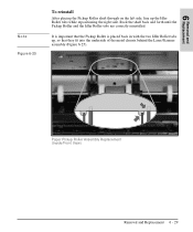
It is placed back in with the two Idler Roller tabs up the Idler Roller tabs while repositioning the right side. Removal and 6 Replacement Note Figure 6-25 To reinstall After placing the Pickup Roller shaft through on the left side, line up , so that the Pickup Roller is important that they fit into the underside of the metal chassis behind the Laser/Scanner assembly (Figure 6-25). Rock the shaft back and forth until the Pickup Roller and the Idler Roller tabs are correctly reinstalled. Paper Pickup Roller Assembly Replacement (Inside/Front View) Removal and Replacement 6 - 29
It is placed back in with the two Idler Roller tabs up the Idler Roller tabs while repositioning the right side. Removal and 6 Replacement Note Figure 6-25 To reinstall After placing the Pickup Roller shaft through on the left side, line up , so that the Pickup Roller is important that they fit into the underside of the metal chassis behind the Laser/Scanner assembly (Figure 6-25). Rock the shaft back and forth until the Pickup Roller and the Idler Roller tabs are correctly reinstalled. Paper Pickup Roller Assembly Replacement (Inside/Front View) Removal and Replacement 6 - 29
Service Manual
Page 103
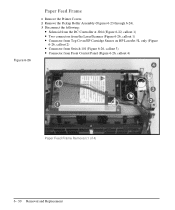
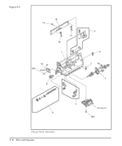
Figure 6-26 Paper Feed Frame 1 Remove the Printer Covers. 2 Remove the Pickup Roller Assembly (Figures 6-23 through 6-24). 3 Disconnect the following: • Solenoid from the DC Controller at J204 (Figure 6-22, callout 1) • Two connectors from the Laser/Scanner (Figure 6-26, callout 1) • Connector from Top Cover/EP Cartridge Sensor on HP LaserJet 5L only (Figure 6-26, callout 2) • Connector from Switch 101 (Figure 6-26, callout 3) • Connector from Front Control Panel (Figure 6-26, callout 4) Paper Feed Frame Removal (1 of 4) 6 - 30 Removal and Replacement
Figure 6-26 Paper Feed Frame 1 Remove the Printer Covers. 2 Remove the Pickup Roller Assembly (Figures 6-23 through 6-24). 3 Disconnect the following: • Solenoid from the DC Controller at J204 (Figure 6-22, callout 1) • Two connectors from the Laser/Scanner (Figure 6-26, callout 1) • Connector from Top Cover/EP Cartridge Sensor on HP LaserJet 5L only (Figure 6-26, callout 2) • Connector from Switch 101 (Figure 6-26, callout 3) • Connector from Front Control Panel (Figure 6-26, callout 4) Paper Feed Frame Removal (1 of 4) 6 - 30 Removal and Replacement
Service Manual
Page 107
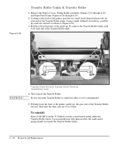
... the Transfer Roller. To reinstall Some of the HP LaserJet 5L Printers contain a small metal spring under the Transfer Roller Guide. 6 - 34 Removal and Replacement Do not touch the Transfer Roller or otherwise allow it to release it off each end of the Transfer Roller shaft. Upon... reinstallation with these models, the small metal spring should rest under the Transfer Roller Guide. Figure 6-30 Transfer Roller Guide & Transfer Roller 1 Remove the Printer Covers, Pickup Roller Assembly (Figures 6-23 through 6-25), and Paper...
... the Transfer Roller. To reinstall Some of the HP LaserJet 5L Printers contain a small metal spring under the Transfer Roller Guide. 6 - 34 Removal and Replacement Do not touch the Transfer Roller or otherwise allow it to release it off each end of the Transfer Roller shaft. Upon... reinstallation with these models, the small metal spring should rest under the Transfer Roller Guide. Figure 6-30 Transfer Roller Guide & Transfer Roller 1 Remove the Printer Covers, Pickup Roller Assembly (Figures 6-23 through 6-25), and Paper...
Service Manual
Page 108
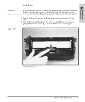
... off its mounting pins. Kick Plate Removal Removal and Replacement 6 - 35 Place the spring aside for Separation Plate disassembly. 1 Remove the Printer Covers and the Pickup Roller Assembly (Figures 6-23 and 6-24). 2 Press the Separation Pad (Figure 6-31). Removal and 6 Replacement Caution Figure 6-31 Kick Plate Be careful working with the Kick...
... off its mounting pins. Kick Plate Removal Removal and Replacement 6 - 35 Place the spring aside for Separation Plate disassembly. 1 Remove the Printer Covers and the Pickup Roller Assembly (Figures 6-23 and 6-24). 2 Press the Separation Pad (Figure 6-31). Removal and 6 Replacement Caution Figure 6-31 Kick Plate Be careful working with the Kick...

Service Manual
Page 110
Separation Pad Removal Removal and Replacement 6 - 37 This will release the Separation Pad (Figure 6-33). 3 Lift the Separation Pad 90 degrees and slide its mounting pins out of the Paper Feed Frame. Removal and 6 Replacement Figure 6-33 Separation Pad 1 Remove the Printer Covers, Pickup Roller Assembly (Figures 6-23 and 6-24), and Kick Plate (Figure 6-31). 2 Lift the bottom of the white plastic tab on the rear of the Paper Feed Frame up slightly and slide it up, toward the top of their retainers.
Separation Pad Removal Removal and Replacement 6 - 37 This will release the Separation Pad (Figure 6-33). 3 Lift the Separation Pad 90 degrees and slide its mounting pins out of the Paper Feed Frame. Removal and 6 Replacement Figure 6-33 Separation Pad 1 Remove the Printer Covers, Pickup Roller Assembly (Figures 6-23 and 6-24), and Kick Plate (Figure 6-31). 2 Lift the bottom of the white plastic tab on the rear of the Paper Feed Frame up slightly and slide it up, toward the top of their retainers.

Service Manual
Page 112
Removal and 6 Replacement Figure 6-35 Feed Assembly The Feed Assembly is located in the Paper Feed Frame. 1 Remove the Printer Covers, Pickup Roller Assembly (Figures 6-23 through 6-25), and Paper Feed Frame (Figures 6-26 through 6-29). 2 Turn the Paper Feed Frame upside down. 3 Remove the Feed Roller Shaft by lifting the plastic tab up (Figure 6-35, callout 1) and sliding it out the side of 3) Removal and Replacement 6 - 39 Feed Assembly Removal (1 of the Paper Feed Frame (Figure 6-35, callout 2).
Removal and 6 Replacement Figure 6-35 Feed Assembly The Feed Assembly is located in the Paper Feed Frame. 1 Remove the Printer Covers, Pickup Roller Assembly (Figures 6-23 through 6-25), and Paper Feed Frame (Figures 6-26 through 6-29). 2 Turn the Paper Feed Frame upside down. 3 Remove the Feed Roller Shaft by lifting the plastic tab up (Figure 6-35, callout 1) and sliding it out the side of 3) Removal and Replacement 6 - 39 Feed Assembly Removal (1 of the Paper Feed Frame (Figure 6-35, callout 2).

Service Manual
Page 140
... paper may not meet HP's paper specifications. Try paper from a fresh ream or a different paper manufacturer. • Replace the toner cartridge. • There may be discontinuities in the input bin. • Readjust the guides to determine if the rollers are dirty. Select different paper. • Clean the Paper Pickup Roller. White Horizontal Line •...
... paper may not meet HP's paper specifications. Try paper from a fresh ream or a different paper manufacturer. • Replace the toner cartridge. • There may be discontinuities in the input bin. • Readjust the guides to determine if the rollers are dirty. Select different paper. • Clean the Paper Pickup Roller. White Horizontal Line •...

Service Manual
Page 148
... motion activities. For both HP LaserJet 5L and 6L Printers: Press SW101 (Figure 7-7, callout 3). 7 Troubleshooting Figure 7-7 Troubleshooting Tools Paper Path Check If paper is not moving through the paper path, you to observe: • Motor rotation • Solenoid action • Kick plate motion • Paper Pickup Roller motion • Drive Roller, Transfer Roller, Fuser Roller and Gear, and...
... motion activities. For both HP LaserJet 5L and 6L Printers: Press SW101 (Figure 7-7, callout 3). 7 Troubleshooting Figure 7-7 Troubleshooting Tools Paper Path Check If paper is not moving through the paper path, you to observe: • Motor rotation • Solenoid action • Kick plate motion • Paper Pickup Roller motion • Drive Roller, Transfer Roller, Fuser Roller and Gear, and...

Service Manual
Page 168
Parts and 8 Diagrams Table 8-6 Internal Components (3 of 3) Ref LaserJet 5LPart No. LaserJet 6LPart No. 1 RB1-7223-000CN RB1-7223-000CN 2 RB1-7246-000CN RB1-7246-000CN 3 RB1-7341-000CN RB1-7341...000CN CK-8006 Qty Description 1 Pickup Roller Grounding Clip 2 Pressure Roller Bushing 1 EP Right Hand Guide #2 1 Pressure Roller 1 Fuser Pressure Plate 1 Transfer Roller Guide 1 Transfer Roller 1 Case Ground Metal 1 EP Right Hand Guide #1 1 EP Left Hand Guide 1 Pressure Roller Gear 1 Right Pressure Roller Housing 1 Left Pressure Roller Housing 1 Pressure Roller Ground Guide 1 Fuser Connector 1...
Parts and 8 Diagrams Table 8-6 Internal Components (3 of 3) Ref LaserJet 5LPart No. LaserJet 6LPart No. 1 RB1-7223-000CN RB1-7223-000CN 2 RB1-7246-000CN RB1-7246-000CN 3 RB1-7341-000CN RB1-7341...000CN CK-8006 Qty Description 1 Pickup Roller Grounding Clip 2 Pressure Roller Bushing 1 EP Right Hand Guide #2 1 Pressure Roller 1 Fuser Pressure Plate 1 Transfer Roller Guide 1 Transfer Roller 1 Case Ground Metal 1 EP Right Hand Guide #1 1 EP Left Hand Guide 1 Pressure Roller Gear 1 Right Pressure Roller Housing 1 Left Pressure Roller Housing 1 Pressure Roller Ground Guide 1 Fuser Connector 1...
Service Manual
Page 171
Figure 8-7 Pickup Roller Assembly 8-18 Parts and Diagrams
Figure 8-7 Pickup Roller Assembly 8-18 Parts and Diagrams

Service Manual
Page 172
Table 8-8 Ref LaserJet 5L Part No. LaserJet 6L Part No. Qty Description 1 RB1-7177-000CN RB1-7177-000CN 1 Paper Feed Frame 2 RY7-5008-000CN RY7-5008-000CN 1 Separation Pad Assembly 3 RY7-5009-000CN RY7-5009-000CN 1 Input Sensor Assembly 4 RG5-1951-000CN RG5-3486-000CN 1 Pickup Roller Assembly 5 RB1-7184-000CN RB1-7184-000CN 1 Pickup Roller Bushing 6 RB1...
Table 8-8 Ref LaserJet 5L Part No. LaserJet 6L Part No. Qty Description 1 RB1-7177-000CN RB1-7177-000CN 1 Paper Feed Frame 2 RY7-5008-000CN RY7-5008-000CN 1 Separation Pad Assembly 3 RY7-5009-000CN RY7-5009-000CN 1 Input Sensor Assembly 4 RG5-1951-000CN RG5-3486-000CN 1 Pickup Roller Assembly 5 RB1-7184-000CN RB1-7184-000CN 1 Pickup Roller Bushing 6 RB1...

Service Manual
Page 184
... Paper Feed Frame Paper Kick Plate (5L) Paper Kick Plate (6L) Paper Pickup Roller Cable Pickup Roller Assembly (5L) Pickup Roller Assembly (6L) Pickup Roller Bushing Pickup Roller Grounding Clip Pressure Roller (5L) Pressure Roller (6L) Pressure Roller Bushing Pressure Roller Gear Pressure Roller Grease Pressure Roller Grounding Guide Right Leg Right Pressure Roller Housing Scanner Cable (5L) Scanner Cable (6L) Part No. RB1-7255-000CN RG5-1995-000CN RG5-3443...
... Paper Feed Frame Paper Kick Plate (5L) Paper Kick Plate (6L) Paper Pickup Roller Cable Pickup Roller Assembly (5L) Pickup Roller Assembly (6L) Pickup Roller Bushing Pickup Roller Grounding Clip Pressure Roller (5L) Pressure Roller (6L) Pressure Roller Bushing Pressure Roller Gear Pressure Roller Grease Pressure Roller Grounding Guide Right Leg Right Pressure Roller Housing Scanner Cable (5L) Scanner Cable (6L) Part No. RB1-7255-000CN RG5-1995-000CN RG5-3443...

Service Manual
Page 186
... Scanner (Exchange) (5L) 8-3 19 Formatter (New) (5L) 8-6 2 Formatter (Exchange) (5L) 8-6 2 Formatter (New) (6L) 8-6 2 Pressure Roller Grease 8-5 Fuser Release Tab 8-3 3 Gear Plate (5L) 8-3 4 Front Gear Case 8-3 5 Memory Door Guide 8-4 1 Case Ground Metal 8-5 8 Fuser Cable Guide 8-4 6 Mylar Guide 8-4 11 Paper Feed Frame 8-7 1 Pickup Roller Bushing 8-7 5 Left Leg 8-7 16 Right Leg 8-7 17 Clutch 8-7 6 Back Ground Clip 8-7 7 Input...
... Scanner (Exchange) (5L) 8-3 19 Formatter (New) (5L) 8-6 2 Formatter (Exchange) (5L) 8-6 2 Formatter (New) (6L) 8-6 2 Pressure Roller Grease 8-5 Fuser Release Tab 8-3 3 Gear Plate (5L) 8-3 4 Front Gear Case 8-3 5 Memory Door Guide 8-4 1 Case Ground Metal 8-5 8 Fuser Cable Guide 8-4 6 Mylar Guide 8-4 11 Paper Feed Frame 8-7 1 Pickup Roller Bushing 8-7 5 Left Leg 8-7 16 Right Leg 8-7 17 Clutch 8-7 6 Back Ground Clip 8-7 7 Input...


