Notebook PC User Guide - Windows 7
Page 123
... critical battery level 56 critical updates, software 96 CyberLink PowerDVD 39 D device drivers HP drivers 76 Windows drivers 77 Diagnostics menu 101 digital card defined 86 inserting 86 removing...100 external audio devices, connecting 40 external drive 78 external monitor port, identifying 7 F f11 111 fan always on 101 firewall 17 firewall software 95 fn key, identifying 5 full system recovery 106 G ...graphics modes, switching 62 H hard drive installing 82 removing 80 replacing 80 hard drive bay, identifying 8 hard drive self test 101 HDMI connecting 42 HDMI port 42 ...
... critical battery level 56 critical updates, software 96 CyberLink PowerDVD 39 D device drivers HP drivers 76 Windows drivers 77 Diagnostics menu 101 digital card defined 86 inserting 86 removing...100 external audio devices, connecting 40 external drive 78 external monitor port, identifying 7 F f11 111 fan always on 101 firewall 17 firewall software 95 fn key, identifying 5 full system recovery 106 G ...graphics modes, switching 62 H hard drive installing 82 removing 80 replacing 80 hard drive bay, identifying 8 hard drive self test 101 HDMI connecting 42 HDMI port 42 ...
Service Guide
Page 8
Electrostatic discharge damage 41 Packaging and transporting guidelines 42 Workstation guidelines 42 Equipment guidelines 43 Component replacement procedures 44 Serial number ...44 Computer feet ...45 Battery ...46 Hard drive ...47 Optical drive ...50 WLAN module ...52 Memory module ...... ...63 TouchPad button board ...64 Modem module ...65 USB board ...67 Power connector ...69 Display assembly ...70 System board ...76 RTC battery ...79 Fan/heat sink assembly ...81 Processor ...85 5 Setup Utility ...89 Computer Setup in Windows 7 ...89 Starting Setup Utility ...89 Using Setup Utility ...89 ...
Electrostatic discharge damage 41 Packaging and transporting guidelines 42 Workstation guidelines 42 Equipment guidelines 43 Component replacement procedures 44 Serial number ...44 Computer feet ...45 Battery ...46 Hard drive ...47 Optical drive ...50 WLAN module ...52 Memory module ...... ...63 TouchPad button board ...64 Modem module ...65 USB board ...67 Power connector ...69 Display assembly ...70 System board ...76 RTC battery ...79 Fan/heat sink assembly ...81 Processor ...85 5 Setup Utility ...89 Computer Setup in Windows 7 ...89 Starting Setup Utility ...89 Using Setup Utility ...89 ...
Service Guide
Page 25
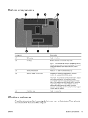
... computer by the governmental agency that regulates wireless devices in your country or region. CAUTION: To prevent an unresponsive system, replace the wireless module only with a wireless module authorized for the internal fan to cool internal components. These antennas are not visible from one or more wireless devices. Bottom components Component (1) (2) Battery...
... computer by the governmental agency that regulates wireless devices in your country or region. CAUTION: To prevent an unresponsive system, replace the wireless module only with a wireless module authorized for the internal fan to cool internal components. These antennas are not visible from one or more wireless devices. Bottom components Component (1) (2) Battery...

Service Guide
Page 31
... ● HP G62 biscotti computer models ● HP G62 biscotti computer models with webcam ● HP G62 silver computer models (for model 1.0 only) ● HP G62 silver computer models with webcam (for model 1.0 only) ● HP G62 matte black computer models (for model 1.0 only) ● HP G62 matte black...Charcoal computer models (for models 1.1 and 1.2 only) ● Imperial blue computer models (for models 1.1 and 1.2 only) Fan/heat sink assembly (includes replacement thermal material) for use in ) High Definition (HD), light-emitting diode (LED) display assembly for use with: ●...
... ● HP G62 biscotti computer models ● HP G62 biscotti computer models with webcam ● HP G62 silver computer models (for model 1.0 only) ● HP G62 silver computer models with webcam (for model 1.0 only) ● HP G62 matte black computer models (for model 1.0 only) ● HP G62 matte black...Charcoal computer models (for models 1.1 and 1.2 only) ● Imperial blue computer models (for models 1.1 and 1.2 only) Fan/heat sink assembly (includes replacement thermal material) for use in ) High Definition (HD), light-emitting diode (LED) display assembly for use with: ●...

Service Guide
Page 47
... enclosure with HDMI card reader for silver computer models (for model 1.0 only) Fan/heat sink assembly (includes replacement thermal material) for use with HD545V discrete systems (for model 1.1 only) 39.6-cm (15.6-in) HD, light-emitting diode display assembly for HP G62 imperial blue computer models (for models 1.1 and 1.2 only) 39.6-cm (15.6-in...
... enclosure with HDMI card reader for silver computer models (for model 1.0 only) Fan/heat sink assembly (includes replacement thermal material) for use with HD545V discrete systems (for model 1.1 only) 39.6-cm (15.6-in) HD, light-emitting diode display assembly for HP G62 imperial blue computer models (for models 1.1 and 1.2 only) 39.6-cm (15.6-in...
Service Guide
Page 88
... from the defective system board and installed on the replacement system board: ● Fan/heat sink assembly (see Fan/heat sink assembly on page 81) ● Processor (see Processor on page 85) Reverse the preceding procedure to install the modem module cable. When replacing the system board, be sure that the following components... (1), and then lift the connector straight up (2) and out of the computer. Reverse this procedure to install the system board. 78 Chapter 4 Removal and replacement procedures ENWW The modem module cable is available using spare part number 595201-001.
... from the defective system board and installed on the replacement system board: ● Fan/heat sink assembly (see Fan/heat sink assembly on page 81) ● Processor (see Processor on page 85) Reverse the preceding procedure to install the modem module cable. When replacing the system board, be sure that the following components... (1), and then lift the connector straight up (2) and out of the computer. Reverse this procedure to install the system board. 78 Chapter 4 Removal and replacement procedures ENWW The modem module cable is available using spare part number 595201-001.

Service Guide
Page 91
... might vary): NOTE: Steps 1 through the operating system. 2. Remove the following components: a. Fan/heat sink assembly Description Fan/heat sink assembly (includes replacement thermal material) for use only with computer models with UMA graphics subsystem memory Fan/heat sink assembly (includes replacement thermal material) for use only with computer models with discrete graphics subsystem memory...
... might vary): NOTE: Steps 1 through the operating system. 2. Remove the following components: a. Fan/heat sink assembly Description Fan/heat sink assembly (includes replacement thermal material) for use only with computer models with UMA graphics subsystem memory Fan/heat sink assembly (includes replacement thermal material) for use only with computer models with discrete graphics subsystem memory...

Service Guide
Page 92
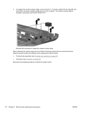
... thermal material located between the fan/heat sink assembly and system board components, it might be necessary to computer models equipped with the front toward you. 82 Chapter 4 Removal and replacement procedures ENWW NOTE: Steps 5 through 8 apply only to move the fan/heat sink assembly from the system... board. 3. Turn the system board right-side up . Disconnect the fan cable from side to side to the system board.
... thermal material located between the fan/heat sink assembly and system board components, it might be necessary to computer models equipped with the front toward you. 82 Chapter 4 Removal and replacement procedures ENWW NOTE: Steps 5 through 8 apply only to move the fan/heat sink assembly from the system... board. 3. Turn the system board right-side up . Disconnect the fan cable from side to side to the system board.
Service Guide
Page 93
.... NOTE: Due to move the fan/heat sink assembly from the system board. 3. 2. Reverse this procedure to detach the assembly. 4. Loosen the three Phillips captive screws (1) and three Phillips spring-loaded captive screws (2) that secure the fan/heat sink assembly. ENWW Component replacement procedures 83 Disconnect the fan cable from side to side to...
.... NOTE: Due to move the fan/heat sink assembly from the system board. 3. 2. Reverse this procedure to detach the assembly. 4. Loosen the three Phillips captive screws (1) and three Phillips spring-loaded captive screws (2) that secure the fan/heat sink assembly. ENWW Component replacement procedures 83 Disconnect the fan cable from side to side to...
Service Guide
Page 94
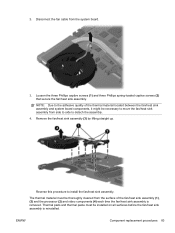
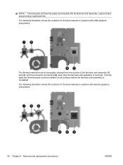
...thermal material on systems with all surfaces before the fan/heat sink assembly is removed. Thermal pads and thermal paste must be installed on systems with discrete graphics subsystems. 84 Chapter 4 Removal and replacement procedures ENWW NOTE: Thermal pads and thermal paste are... included with UMA graphics subsystems. The thermal material must be thoroughly cleaned from the surface of the fan/heat sink assembly (1) and (3), and the processor ...
...thermal material on systems with all surfaces before the fan/heat sink assembly is removed. Thermal pads and thermal paste must be installed on systems with discrete graphics subsystems. 84 Chapter 4 Removal and replacement procedures ENWW NOTE: Thermal pads and thermal paste are... included with UMA graphics subsystems. The thermal material must be thoroughly cleaned from the surface of the fan/heat sink assembly (1) and (3), and the processor ...

Service Guide
Page 96
... power cord from the AC outlet and then disconnecting the AC adapter from the computer. 4. Speaker assembly (see Fan/heat sink assembly on page 50) c. Fan/heat sink assembly (see Speaker assembly on page 47) b. Shut down through the operating system. 2. Optical drive... (see Display assembly on page 76) h. If you hear a click. 86 Chapter 4 Removal and replacement procedures ENWW Display assembly (see Optical ...
... power cord from the AC outlet and then disconnecting the AC adapter from the computer. 4. Speaker assembly (see Fan/heat sink assembly on page 50) c. Fan/heat sink assembly (see Speaker assembly on page 47) b. Shut down through the operating system. 2. Optical drive... (see Display assembly on page 76) h. If you hear a click. 86 Chapter 4 Removal and replacement procedures ENWW Display assembly (see Optical ...

Service Guide
Page 144
... spare part numbers 22, 76 System Configuration menu 93, 98 system failure or instability 107 system fan 98 system information 92, 96 system recovery 111 system resources 106 system restore points 107, 111 T thermal paste, replacement 83, 84 tools required 39 top cover removal 59 spare part number 21, 59 TouchPad buttons...
... spare part numbers 22, 76 System Configuration menu 93, 98 system failure or instability 107 system fan 98 system information 92, 96 system recovery 111 system resources 106 system restore points 107, 111 T thermal paste, replacement 83, 84 tools required 39 top cover removal 59 spare part number 21, 59 TouchPad buttons...


