

Installation Instructions
Page 1
...*765003-001* 765003-001 NOTE: An industry standard server shelf is subject to install and use the Desktop Mini Rack Mount Tray Kit. Installation Instructions HP Desktop Mini Rack Mount Tray Kit Remove the backing from the adhesive strips on the bottom of seven U spacing. Copyright ...© 2015 Hewlett-Packard Development Company, L.P. CAUTION: You must pull the arm back before inserting the Desktop Mini or the arm...
...*765003-001* 765003-001 NOTE: An industry standard server shelf is subject to install and use the Desktop Mini Rack Mount Tray Kit. Installation Instructions HP Desktop Mini Rack Mount Tray Kit Remove the backing from the adhesive strips on the bottom of seven U spacing. Copyright ...© 2015 Hewlett-Packard Development Company, L.P. CAUTION: You must pull the arm back before inserting the Desktop Mini or the arm...

Installation Instructions 1
Page 1
... go to the system, ensure that the power cord is available from HP (PN 166527001 or 166527-002). For Desktop Mini models without notice. Installing a second expansion module (due to change without enhanced power (800 G1, 600 G1, 705 G1), connect the USB cable to operate a rear I/O or hard drive +... head. NOTE: For the second expansion module, connect the USB cable to the Desktop Mini. A tamper-resistant FailSafe key is subject to power restrictions the 600 G1, 705 G1, and 800 G1 models do so may expose you begin Before installing the expansion module, turn off power to...
... go to the system, ensure that the power cord is available from HP (PN 166527001 or 166527-002). For Desktop Mini models without notice. Installing a second expansion module (due to change without enhanced power (800 G1, 600 G1, 705 G1), connect the USB cable to operate a rear I/O or hard drive +... head. NOTE: For the second expansion module, connect the USB cable to the Desktop Mini. A tamper-resistant FailSafe key is subject to power restrictions the 600 G1, 705 G1, and 800 G1 models do so may expose you begin Before installing the expansion module, turn off power to...

Implementing Out-Of-Band PC Management with DASH on Business Systems with AMD Chipset
Page 4
Supported desktop models Broadcom NIC Systems HP EliteDesk 705 G2 Desktop Mini HP EliteOne 705 G2 All in One HP EliteDesk 705 G2 Microtower HP EliteDesk 705 G2 Small Form Factor HP EliteDesk 705 G1 Desktop Mini HP EliteOne 705 G1 All in One HP EliteDesk 705 G1 Microtower HP EliteDesk 705 G1 Small Form Factor Realtek NIC systems HP EliteBook 745 G6 Notebook PC HP EliteBook 735 G6 Notebook PC HP EliteBook 755 G5 Notebook PC HP EliteBook 745 G5 Notebook PC...
Supported desktop models Broadcom NIC Systems HP EliteDesk 705 G2 Desktop Mini HP EliteOne 705 G2 All in One HP EliteDesk 705 G2 Microtower HP EliteDesk 705 G2 Small Form Factor HP EliteDesk 705 G1 Desktop Mini HP EliteOne 705 G1 All in One HP EliteDesk 705 G1 Microtower HP EliteDesk 705 G1 Small Form Factor Realtek NIC systems HP EliteBook 745 G6 Notebook PC HP EliteBook 735 G6 Notebook PC HP EliteBook 755 G5 Notebook PC HP EliteBook 745 G5 Notebook PC...

Installation Instructions
Page 1
...003* 765004-003 The Security/Dual VESA Sleeve can be mounted to the following monitors: HP V193B, HP P232 Security bracket for 400/600/705/ 800 Desktop Mini models Security bracket for the 260 Desktop Mini model 8mm ladder screws, Torx/flat head Install in the sleeve with the screw holes on... the sleeve and the padlock loop for your model 2. Installation Instructions HP Desktop Mini Security/Dual VESA Sleeve ...
...003* 765004-003 The Security/Dual VESA Sleeve can be mounted to the following monitors: HP V193B, HP P232 Security bracket for 400/600/705/ 800 Desktop Mini models Security bracket for the 260 Desktop Mini model 8mm ladder screws, Torx/flat head Install in the sleeve with the screw holes on... the sleeve and the padlock loop for your model 2. Installation Instructions HP Desktop Mini Security/Dual VESA Sleeve ...

Hardware Reference Guide
Page 3
CAUTION: Text set off in this manner indicates that failure to equipment or loss of life. NOTE: Text set off in this manner indicates that failure to follow directions could result in damage to follow directions could result in this manner provides important supplemental information. About This Book This guide provides basic information for upgrading the HP Desktop Mini Business PC. WARNING! Text set off in bodily harm or loss of information. iii
CAUTION: Text set off in this manner indicates that failure to equipment or loss of life. NOTE: Text set off in this manner indicates that failure to follow directions could result in damage to follow directions could result in this manner provides important supplemental information. About This Book This guide provides basic information for upgrading the HP Desktop Mini Business PC. WARNING! Text set off in bodily harm or loss of information. iii

Hardware Reference Guide
Page 13
Rear panel components (ProDesk 400) 7 Rear panel components (ProDesk 400) 1 DisplayPort Monitor Connector 2 VGA Monitor Connector 4 USB 2.0 Ports (black) 5 RJ-45 Network Connector 3 USB 2.0 Ports with enhanced power (black) 6 Power Cord Connector NOTE: The two upper USB ports have additional power capacity to support the Desktop Mini External Expansion Sleeves. NOTE: The two lower USB ports support wake-from-sleep states if that option is enabled in the Computer Setup (F10) utility.
Rear panel components (ProDesk 400) 7 Rear panel components (ProDesk 400) 1 DisplayPort Monitor Connector 2 VGA Monitor Connector 4 USB 2.0 Ports (black) 5 RJ-45 Network Connector 3 USB 2.0 Ports with enhanced power (black) 6 Power Cord Connector NOTE: The two upper USB ports have additional power capacity to support the Desktop Mini External Expansion Sleeves. NOTE: The two lower USB ports support wake-from-sleep states if that option is enabled in the Computer Setup (F10) utility.

Maintenance and Service Guide
Page 1
Maintenance and Service Guide HP EliteDesk 705 G1 Microtower HP EliteDesk 705 G1 Small Form Factor HP EliteDesk 705 G1 Desktop Mini
Maintenance and Service Guide HP EliteDesk 705 G1 Microtower HP EliteDesk 705 G1 Small Form Factor HP EliteDesk 705 G1 Desktop Mini

Maintenance and Service Guide
Page 5
... boards ...16 Small Form Factor (SFF) chassis spare parts ...17 Computer major components ...17 Cables ...19 Misc parts ...20 Drives ...22 Misc boards ...23 Desktop Mini (DM) chassis spare parts ...24 Computer major components ...24 Cables ...25 Misc parts ...26 Drives ...27 3 Routine care, SATA drive guidelines, and disassembly preparation 28...
... boards ...16 Small Form Factor (SFF) chassis spare parts ...17 Computer major components ...17 Cables ...19 Misc parts ...20 Drives ...22 Misc boards ...23 Desktop Mini (DM) chassis spare parts ...24 Computer major components ...24 Cables ...25 Misc parts ...26 Drives ...27 3 Routine care, SATA drive guidelines, and disassembly preparation 28...

Maintenance and Service Guide
Page 8
desktop mini (DM) chassis 121 Preparation for disassembly ...121 Access panel ...122 Hard drive ...123 Speaker ...126 Front bezel ...128 Memory ...129 SODIMMs ...129 DDR3-SDRAM SODIMMs ......
desktop mini (DM) chassis 121 Preparation for disassembly ...121 Access panel ...122 Hard drive ...123 Speaker ...126 Front bezel ...128 Memory ...129 SODIMMs ...129 DDR3-SDRAM SODIMMs ......

Maintenance and Service Guide
Page 12
Desktop mini NOTE: The desktop mini can be used in a tower orientation or a desktop orientation. 2 Chapter 1 Product Features
Desktop mini NOTE: The desktop mini can be used in a tower orientation or a desktop orientation. 2 Chapter 1 Product Features
Maintenance and Service Guide
Page 15
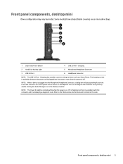
... Refer to the Maintenance and Service Guide to use the connector for a microphone Line-In device or a headphone. Front panel components, desktop mini Drive configuration may vary by double-clicking the Audio Manager icon in the Windows taskbar. Charging 2 Hard Drive Activity Light 5 Microphone/Headphone Connector...the computer and it is on. Charging also provides current to charge a device such as a Smart Phone. Front panel components, desktop mini 5 You can reconfigure the connector at any time by model. The charging current is available whenever the power cord is plugged into the...
... Refer to the Maintenance and Service Guide to use the connector for a microphone Line-In device or a headphone. Front panel components, desktop mini Drive configuration may vary by double-clicking the Audio Manager icon in the Windows taskbar. Charging 2 Hard Drive Activity Light 5 Microphone/Headphone Connector...the computer and it is on. Charging also provides current to charge a device such as a Smart Phone. Front panel components, desktop mini 5 You can reconfigure the connector at any time by model. The charging current is available whenever the power cord is plugged into the...

Maintenance and Service Guide
Page 18
Rear panel components, desktop mini 1 DisplayPort Monitor Connectors 2 VGA Monitor Connector 5 USB 2.0 Ports (black) 6 RJ-45 Network Connector 3 Line-Out Connector for powered audio devices 7 Power Cord Connector (green) 4 USB 3.0 Ports (blue) 8 Chapter 1 Product Features
Rear panel components, desktop mini 1 DisplayPort Monitor Connectors 2 VGA Monitor Connector 5 USB 2.0 Ports (black) 6 RJ-45 Network Connector 3 Line-Out Connector for powered audio devices 7 Power Cord Connector (green) 4 USB 3.0 Ports (blue) 8 Chapter 1 Product Features

Maintenance and Service Guide
Page 31
Item (1) (2) (3) (4) (5) (6) (7) (8) (9) * * * * * * Description Fan sink (includes replacement thermal material) Baffle Speaker 2.5-in drive adapter Card reader, 15-in-1 Adapter, USB 3.0 to USB 2.0 (for use with card reader) Solenoid lock Clamp lock, includes universal cable (plate not included) Hood sensor Chassis stand Antenna Hard drive conversion bracket Grommet, hard drive isolation, blue Mouse USB, optical Washable Wireless USB, laser PS2, optical Keyboard PS/2 USB USB, mini Washable Smart card Small Form Factor (SFF) chassis spare parts 21
Item (1) (2) (3) (4) (5) (6) (7) (8) (9) * * * * * * Description Fan sink (includes replacement thermal material) Baffle Speaker 2.5-in drive adapter Card reader, 15-in-1 Adapter, USB 3.0 to USB 2.0 (for use with card reader) Solenoid lock Clamp lock, includes universal cable (plate not included) Hood sensor Chassis stand Antenna Hard drive conversion bracket Grommet, hard drive isolation, blue Mouse USB, optical Washable Wireless USB, laser PS2, optical Keyboard PS/2 USB USB, mini Washable Smart card Small Form Factor (SFF) chassis spare parts 21

Maintenance and Service Guide
Page 34
For complete and current information on supported parts for your computer, go to http://partsurfer.hp.com, select your country or region, and then follow the on-screen instructions. Desktop Mini (DM) chassis spare parts NOTE: HP continually improves and changes product parts. Computer major components Item (1) (2) (3) Description Access panel Front bezel Stand Power...
For complete and current information on supported parts for your computer, go to http://partsurfer.hp.com, select your country or region, and then follow the on-screen instructions. Desktop Mini (DM) chassis spare parts NOTE: HP continually improves and changes product parts. Computer major components Item (1) (2) (3) Description Access panel Front bezel Stand Power...

Maintenance and Service Guide
Page 37
... solid-state drive (SSD), Self-encrypting Drive (SED), SATA 6.0 120 GB solid-state drive (SSD), SATA 6.0, MLC M.2 drive 128 GB solid-state drive (SSD), M.2 Desktop Mini (DM) chassis spare parts 27
... solid-state drive (SSD), Self-encrypting Drive (SED), SATA 6.0 120 GB solid-state drive (SSD), SATA 6.0, MLC M.2 drive 128 GB solid-state drive (SSD), M.2 Desktop Mini (DM) chassis spare parts 27

Maintenance and Service Guide
Page 131
... 5. WARNING! Remove/disengage any external devices. In some systems the cooling fan is on page 28 for your computer, go to http://partsurfer.hp.com, select your country or region, and then follow the on all removable media, such as the system is always present on a stand,... remove the computer from the computer. 3. desktop mini (DM) chassis Adherence to verify that prohibit opening the computer. 2. Regardless of sharp edges inside the chassis. Disconnect the power cord from the ...
... 5. WARNING! Remove/disengage any external devices. In some systems the cooling fan is on page 28 for your computer, go to http://partsurfer.hp.com, select your country or region, and then follow the on all removable media, such as the system is always present on a stand,... remove the computer from the computer. 3. desktop mini (DM) chassis Adherence to verify that prohibit opening the computer. 2. Regardless of sharp edges inside the chassis. Disconnect the power cord from the ...

Maintenance and Service Guide
Page 132
To install the access panel, reverse the removal procedure. 122 Chapter 6 Removal and replacement procedures - desktop mini (DM) chassis Access panel 1. Loosen the thumbscrew on page 121). 2. Prepare the computer for disassembly (Preparation for disassembly on the rear of the computer (1) then slide the panel forward and lift if off the computer (2).
To install the access panel, reverse the removal procedure. 122 Chapter 6 Removal and replacement procedures - desktop mini (DM) chassis Access panel 1. Loosen the thumbscrew on page 121). 2. Prepare the computer for disassembly (Preparation for disassembly on the rear of the computer (1) then slide the panel forward and lift if off the computer (2).

Maintenance and Service Guide
Page 134
4. While pulling the release lever out, slide the drive back until it stops, then lift the drive up and out of the hard drive outward (1). Pull the release lever next to the rear of the bay (2). 5. To install a hard drive, you must transfer the silver and blue isolation mounting guide screws from the old drive to the new hard drive. 6. Transfer the drive cables from the old hard drive to the new drive. 124 Chapter 6 Removal and replacement procedures - desktop mini (DM) chassis
4. While pulling the release lever out, slide the drive back until it stops, then lift the drive up and out of the hard drive outward (1). Pull the release lever next to the rear of the bay (2). 5. To install a hard drive, you must transfer the silver and blue isolation mounting guide screws from the old drive to the new hard drive. 6. Transfer the drive cables from the old hard drive to the new drive. 124 Chapter 6 Removal and replacement procedures - desktop mini (DM) chassis

Maintenance and Service Guide
Page 136
Remove the access panel (Access panel on page 121). 2. desktop mini (DM) chassis To remove the speaker: 1. Disconnect the speaker cable from the system board connector (2). 126 Chapter 6 Removal and replacement procedures - From the front of the computer behind the front bezel, inside the chassis. Speaker A single speaker is secured by a white peg that you pull out to remove the white peg that secures the speaker (1). 4. Prepare the computer for disassembly (Preparation for disassembly on page 122). 3. It is located on the left side of the computer, pull to release.
Remove the access panel (Access panel on page 121). 2. desktop mini (DM) chassis To remove the speaker: 1. Disconnect the speaker cable from the system board connector (2). 126 Chapter 6 Removal and replacement procedures - From the front of the computer behind the front bezel, inside the chassis. Speaker A single speaker is secured by a white peg that you pull out to remove the white peg that secures the speaker (1). 4. Prepare the computer for disassembly (Preparation for disassembly on page 122). 3. It is located on the left side of the computer, pull to release.

Maintenance and Service Guide
Page 138
Remove the bezel from the access panel. desktop mini (DM) chassis Pull down so you can access the inside of the bezel (2). 6. Disengage the tabs on the bezel (1). 5. Position the access panel upside-down ...
Remove the bezel from the access panel. desktop mini (DM) chassis Pull down so you can access the inside of the bezel (2). 6. Disengage the tabs on the bezel (1). 5. Position the access panel upside-down ...


