
HP Workstation c8000 Technical Reference Guide
Page 1
Technical Reference Guide HP workstation c8000 Document Part Number: 5969-3188 Second Edition July 2004 This manual contains an overview of system specifications, instructions for removing and replacing system components, information on configuring your system using the included tools and interfaces, and detailed troubleshooting information.
Technical Reference Guide HP workstation c8000 Document Part Number: 5969-3188 Second Edition July 2004 This manual contains an overview of system specifications, instructions for removing and replacing system components, information on configuring your system using the included tools and interfaces, and detailed troubleshooting information.

HP Workstation c8000 Technical Reference Guide
Page 2
...information in this material. Nothing herein should be liable for technical or editorial errors or omissions contained herein or for HP products are registered trademarks or trademarks of information. © Copyright 2004 Hewlett-Packard Development Company, L.P. Hewlett-Packard...174; and Itanium® are used under license. and other product names mentioned herein may be trademarks of Intel Corporation in this manner indicates that is provided "as constituting an additional warranty. Technical Reference Guide HP workstation c8000 Second Edition (July 2004) Document...
...information in this material. Nothing herein should be liable for technical or editorial errors or omissions contained herein or for HP products are registered trademarks or trademarks of information. © Copyright 2004 Hewlett-Packard Development Company, L.P. Hewlett-Packard...174; and Itanium® are used under license. and other product names mentioned herein may be trademarks of Intel Corporation in this manner indicates that is provided "as constituting an additional warranty. Technical Reference Guide HP workstation c8000 Second Edition (July 2004) Document...

HP Workstation c8000 Technical Reference Guide
Page 3
... avoid electrical shock and harm to recharge, disassemble, or burn an old battery. If a Power Protection Device is fitted to HP so that does not contain any heavy metals. For your safety, never attempt to your eyes by metallic particulate contamination. The ...Burn Injuries. Since metallic contamination can cause permanent or intermittent failures on your electronic equipment, Hewlett-Packard strongly recommends that your computer using its on the DVD for metallic particulate contamination before installation of pure metal can be accepted free of batteries in this problem is...
... avoid electrical shock and harm to recharge, disassemble, or burn an old battery. If a Power Protection Device is fitted to HP so that does not contain any heavy metals. For your safety, never attempt to your eyes by metallic particulate contamination. The ...Burn Injuries. Since metallic contamination can cause permanent or intermittent failures on your electronic equipment, Hewlett-Packard strongly recommends that your computer using its on the DVD for metallic particulate contamination before installation of pure metal can be accepted free of batteries in this problem is...

HP Workstation c8000 Technical Reference Guide
Page 4
... all equipment and disconnect the power cable before using your clothes touch any accessory card. The remainder is taken for recycling when it reaches the end of the system unit while you require more extensive ergonomics information at: www.hp.com/ergo NOTE: Recycling Your System. To equalize... Office. As many parts as possible and with care. Ä CAUTION: Information on top of its useful life. If you are removing the card from the bag. HP has a product take -back program, contact your local dealer or your old system for batteries and other potential toxic substances,...
... all equipment and disconnect the power cable before using your clothes touch any accessory card. The remainder is taken for recycling when it reaches the end of the system unit while you require more extensive ergonomics information at: www.hp.com/ergo NOTE: Recycling Your System. To equalize... Office. As many parts as possible and with care. Ä CAUTION: Information on top of its useful life. If you are removing the card from the bag. HP has a product take -back program, contact your local dealer or your old system for batteries and other potential toxic substances,...

HP Workstation c8000 Technical Reference Guide
Page 9
... (page 2-6). ■ Features and overview at: http://www.hp.com/workstations/risc/c8000 ■ Supported accessories and components at: http://partsurfer.hp.com Feature Processor Firmware Operating system Main memory Hard drive(s) Description One or two HP PA-8800 processor modules 8 MB flash EEPROM Configured using Boot Console Handler (BCH) HP-UX 11i v1 Capacity: • Minimum 1 GB...
... (page 2-6). ■ Features and overview at: http://www.hp.com/workstations/risc/c8000 ■ Supported accessories and components at: http://partsurfer.hp.com Feature Processor Firmware Operating system Main memory Hard drive(s) Description One or two HP PA-8800 processor modules 8 MB flash EEPROM Configured using Boot Console Handler (BCH) HP-UX 11i v1 Capacity: • Minimum 1 GB...

HP Workstation c8000 Technical Reference Guide
Page 20
... Bits: 1 (one) ❏ Flow Control: XON/XOFF 4. Paths All devices in the HP workstation c8000 are represented by paths in the BCH. Turn on the workstation. To identify the correct slot or disk drive, use the following tables. Accessory Card Slots Slot Path 1 PCI (33 MHz, 32 bit, half-...2 0/3/2/0.0.1 IDE optical drive 1 0/3/2/0.1.0 IDE optical drive 2 0/3/2/0.1.1 Hardware Connection IDE 0, master IDE 0, slave IDE 1, master IDE 1, slave 2-2 Technical Reference Guide Using the terminal emulation software, connect to the serial console device. System Configuration 3.
... Bits: 1 (one) ❏ Flow Control: XON/XOFF 4. Paths All devices in the HP workstation c8000 are represented by paths in the BCH. Turn on the workstation. To identify the correct slot or disk drive, use the following tables. Accessory Card Slots Slot Path 1 PCI (33 MHz, 32 bit, half-...2 0/3/2/0.0.1 IDE optical drive 1 0/3/2/0.1.0 IDE optical drive 2 0/3/2/0.1.1 Hardware Connection IDE 0, master IDE 0, slave IDE 1, master IDE 1, slave 2-2 Technical Reference Guide Using the terminal emulation software, connect to the serial console device. System Configuration 3.
HP Workstation c8000 Technical Reference Guide
Page 26
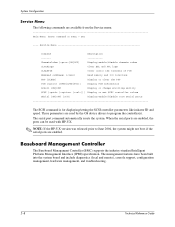
These parameters are used with HP-UX. ✎ NOTE: If the HP-UX version was released prior to program the controller(s). Baseboard Management Controller The Baseboard Management Controller (BMC) supports the industry-standard Intelligent Platform Management Interface (... SCSI command is for displaying/setting the SCSI controller parameters like initiator ID and speed. When the serial ports are enabled, the ports can be used by the OS device drivers to June 2004, the system might not boot if the serial ports are available from the Service menu. The management...
These parameters are used with HP-UX. ✎ NOTE: If the HP-UX version was released prior to program the controller(s). Baseboard Management Controller The Baseboard Management Controller (BMC) supports the industry-standard Intelligent Platform Management Interface (... SCSI command is for displaying/setting the SCSI controller parameters like initiator ID and speed. When the serial ports are enabled, the ports can be used by the OS device drivers to June 2004, the system might not boot if the serial ports are available from the Service menu. The management...

HP Workstation c8000 Technical Reference Guide
Page 38
... LED (page 1-7) turns off the workstation and unplug the power cord from the AC power outlet. You can be: ■ 256 MB ■ 512 MB ■ 1 GB ■ 2 GB ■ 4 GB DIMMs must be installed in a static-free container for future use the BCH Information menu (see : http://partsurfer.hp.com Removing Memory Modules 1. Press... ensure that memory modules are not damaged during removal or installation, power off before removing or installing memory. 2. Installing or Replacing Parts Memory Modules The HP workstation c8000 has eight memory slots for your system...
... LED (page 1-7) turns off the workstation and unplug the power cord from the AC power outlet. You can be: ■ 256 MB ■ 512 MB ■ 1 GB ■ 2 GB ■ 4 GB DIMMs must be installed in a static-free container for future use the BCH Information menu (see : http://partsurfer.hp.com Removing Memory Modules 1. Press... ensure that memory modules are not damaged during removal or installation, power off before removing or installing memory. 2. Installing or Replacing Parts Memory Modules The HP workstation c8000 has eight memory slots for your system...

HP Workstation c8000 Technical Reference Guide
Page 39
...memory modules are seated properly. 3. Replace the airflow guide and system access panel, reconnect all LEDs on the system. 4. Check the memory configuration using the BCH Information menu (page 2-6). Make sure DIMMs are inserted fully and that the DIMMs are keyed and can only be loaded in this order... try to their fully upright position. Holding the DIMM by its left and right edges, insert it into a slot backwards. DIMM Installation Guidelines The HP workstation c8000 has eight memory DIMM slots organized as four a/b pairs: 0a and 0b, 1a and 1b, 2a and 2b, 3a and 3b. ❏ ...
...memory modules are seated properly. 3. Replace the airflow guide and system access panel, reconnect all LEDs on the system. 4. Check the memory configuration using the BCH Information menu (page 2-6). Make sure DIMMs are inserted fully and that the DIMMs are keyed and can only be loaded in this order... try to their fully upright position. Holding the DIMM by its left and right edges, insert it into a slot backwards. DIMM Installation Guidelines The HP workstation c8000 has eight memory DIMM slots organized as four a/b pairs: 0a and 0b, 1a and 1b, 2a and 2b, 3a and 3b. ❏ ...

HP Workstation c8000 Technical Reference Guide
Page 43
... bulkhead blank Technical Reference Guide 3-15 From the inside of the case, push on your graphics card, visit the manufacturer's web site or refer to use. If the slot is in the slot you want to the graphics documentation included in the acccessory kit. To install an accessory or graphics card...
... bulkhead blank Technical Reference Guide 3-15 From the inside of the case, push on your graphics card, visit the manufacturer's web site or refer to use. If the slot is in the slot you want to the graphics documentation included in the acccessory kit. To install an accessory or graphics card...

HP Workstation c8000 Technical Reference Guide
Page 44
... and reconnect all cables. 5. Turn on page 3-13). 4. Installing or Replacing Parts 2. Plugging in place. (See the figure on the system and check the configuration using the BCH Information menu (page 2-6). 3-16 Technical Reference Guide
... and reconnect all cables. 5. Turn on page 3-13). 4. Installing or Replacing Parts 2. Plugging in place. (See the figure on the system and check the configuration using the BCH Information menu (page 2-6). 3-16 Technical Reference Guide

HP Workstation c8000 Technical Reference Guide
Page 46
... the power and audio cables to three optical drives. Connect the IDE cable to "Removing an Optical Drive" on page 3-17. 3. the gray connector is used to connect the hard drives, the other to connect up to the optical drive. 4. If you have IDE hard drives installed, one cable is for...
... the power and audio cables to three optical drives. Connect the IDE cable to "Removing an Optical Drive" on page 3-17. 3. the gray connector is used to connect the hard drives, the other to connect up to the optical drive. 4. If you have IDE hard drives installed, one cable is for...

HP Workstation c8000 Technical Reference Guide
Page 47
Hard Drives Removing a Hard Drive 1. Replace the access panels and reconnect all cables, and remove the system access panel. 2. Disconnect the hard drive IDE or SCSI cable 1 and power connector 2. 3. Installing or Replacing Parts 5. Turn off the system, disconnect all cables. 6. Squeeze inward on the blue release clips located on , then check the configuration using the BCH Information menu (page 2-6). Removing a hard drive Technical Reference Guide 3-19 Then, pull outward to remove the drive from the system 4. Turn the system on the sides of the drive 3.
Hard Drives Removing a Hard Drive 1. Replace the access panels and reconnect all cables, and remove the system access panel. 2. Disconnect the hard drive IDE or SCSI cable 1 and power connector 2. 3. Installing or Replacing Parts 5. Turn off the system, disconnect all cables. 6. Squeeze inward on the blue release clips located on , then check the configuration using the BCH Information menu (page 2-6). Removing a hard drive Technical Reference Guide 3-19 Then, pull outward to remove the drive from the system 4. Turn the system on the sides of the drive 3.

HP Workstation c8000 Technical Reference Guide
Page 48
Snap the drive inside the drive tray to attach rails to the drive. Pull outwards on , then check the configuration using the BCH Information menu (page 2-6). 3-20 Technical Reference Guide Then attach the power 2 and IDE or SCSI cable 3 to the hard drive. Pull forward to ...
Snap the drive inside the drive tray to attach rails to the drive. Pull outwards on , then check the configuration using the BCH Information menu (page 2-6). 3-20 Technical Reference Guide Then attach the power 2 and IDE or SCSI cable 3 to the hard drive. Pull forward to ...

HP Workstation c8000 Technical Reference Guide
Page 50
Installing or Replacing Parts SCSI Drives The HP workstation c8000 supports up to four SCSI hard drives attached to terminate the SCSI chain. Set the SCSI ID on your drive(s): ❏ Drive 1 ID=3 ❏ Drive 2 ... documentation provided with the drive for each SCSI ID. Install drives in bays in the following order 3: ❏ Use bay 3d for Drive 1 ❏ Use bay 3b for Drive 2 ❏ Use bay 3c for Drive 3 ❏ Use bay 3a for more information on the system board 1 and attach the cable 2 to the SCSI A connector...
Installing or Replacing Parts SCSI Drives The HP workstation c8000 supports up to four SCSI hard drives attached to terminate the SCSI chain. Set the SCSI ID on your drive(s): ❏ Drive 1 ID=3 ❏ Drive 2 ... documentation provided with the drive for each SCSI ID. Install drives in bays in the following order 3: ❏ Use bay 3d for Drive 1 ❏ Use bay 3b for Drive 2 ❏ Use bay 3c for Drive 3 ❏ Use bay 3a for more information on the system board 1 and attach the cable 2 to the SCSI A connector...

HP Workstation c8000 Technical Reference Guide
Page 51
... current hard drive for a picture showing where on the system board to the hard drive activity LED connector on the system board. If two devices use ID 0, the system will not boot. ■ If you are adding a SCSI hard drive to your system, you may need to 15 devices...SCSI controller card. Refer to "System Board Components and Connectors" on -board SCSI controller or to the built-in the chassis using a regular screwdriver. External SCSI Devices You can use external devices. Insert a flat-head screwdriver into the rectangular hole and twist the metal until the panel comes out. Remove ...
... current hard drive for a picture showing where on the system board to the hard drive activity LED connector on the system board. If two devices use ID 0, the system will not boot. ■ If you are adding a SCSI hard drive to your system, you may need to 15 devices...SCSI controller card. Refer to "System Board Components and Connectors" on -board SCSI controller or to the built-in the chassis using a regular screwdriver. External SCSI Devices You can use external devices. Insert a flat-head screwdriver into the rectangular hole and twist the metal until the panel comes out. Remove ...

HP Workstation c8000 Technical Reference Guide
Page 53
... the system, disconnect all components 1, including the: ❏ hard drives ❏ optical drives ❏ graphics card ❏ system board NOTE: Use caution when lifting the power supply because there are cables below the power supply (illustrated on the next page) that connect to the power module(s) ...and remove the system access panel and airflow guide. 2. Installing or Replacing Parts Power Supply Before replacing the power supply, you can use the Built-In Self-Test (BIST) feature to Chapter 4, "Troubleshooting", for more information. Slide the power supply toward the front of...
... the system, disconnect all components 1, including the: ❏ hard drives ❏ optical drives ❏ graphics card ❏ system board NOTE: Use caution when lifting the power supply because there are cables below the power supply (illustrated on the next page) that connect to the power module(s) ...and remove the system access panel and airflow guide. 2. Installing or Replacing Parts Power Supply Before replacing the power supply, you can use the Built-In Self-Test (BIST) feature to Chapter 4, "Troubleshooting", for more information. Slide the power supply toward the front of...

HP Workstation c8000 Technical Reference Guide
Page 58
Pull the switch out of the slot by pushing it , then remove the sensor from the system: a. Pull up on the head of the plastic push rivet and remove it in place 1 2 3. 3-30 Unscrewing the front control module Technical Reference Guide Removing the chassis intrusion switch 4. Slide the switch out of the opening 2. c. Use a Torx T-15 or slot screwdriver to remove the screws holding the front control module in the direction shown 1. Installing or Replacing Parts 3. b. Remove the panel from the system 5. Remove the chassis intrusion switch and temperature sensor: a.
Pull the switch out of the slot by pushing it , then remove the sensor from the system: a. Pull up on the head of the plastic push rivet and remove it in place 1 2 3. 3-30 Unscrewing the front control module Technical Reference Guide Removing the chassis intrusion switch 4. Slide the switch out of the opening 2. c. Use a Torx T-15 or slot screwdriver to remove the screws holding the front control module in the direction shown 1. Installing or Replacing Parts 3. b. Remove the panel from the system 5. Remove the chassis intrusion switch and temperature sensor: a.

HP Workstation c8000 Technical Reference Guide
Page 59
... switch: a. Replace the temperature sensor and attach it snaps into the system chassis. Insert the switch into the housing and slide in the system and use a Torx T-15 or slot screwdriver to the appropriate components and connectors and reconnect all power cables and turn on the chassis. Replace the I/O panel in...
... switch: a. Replace the temperature sensor and attach it snaps into the system chassis. Insert the switch into the housing and slide in the system and use a Torx T-15 or slot screwdriver to the appropriate components and connectors and reconnect all power cables and turn on the chassis. Replace the I/O panel in...

HP Workstation c8000 Technical Reference Guide
Page 61
Remove the processor power module (CPU0 is shown): a. Removing a processor power module Technical Reference Guide 3-33 b. Slide the processor power module towards the rear of the system until it stops, then lift it out of the system. Use the special processor tool (included with your processor kit) to the system. 1. Installing or Replacing Parts Remove the Processor (for Replacement) Ä CAUTION: You must follow these steps exactly and in the correct sequence to avoid serious damage to remove the two screws 1 from the processor power module.
Remove the processor power module (CPU0 is shown): a. Removing a processor power module Technical Reference Guide 3-33 b. Slide the processor power module towards the rear of the system until it stops, then lift it out of the system. Use the special processor tool (included with your processor kit) to the system. 1. Installing or Replacing Parts Remove the Processor (for Replacement) Ä CAUTION: You must follow these steps exactly and in the correct sequence to avoid serious damage to remove the two screws 1 from the processor power module.


