
HP Workstation c8000 Technical Reference Guide
Page 6
Contents Troubleshooting E-Support 4-2 Troubleshooting Overview 4-2 Identifying and Diagnosing Hardware Problems 4-2 LEDs 4-3 BCH Error and Warning Messages 4-12 Displaying PIM Information 4-12 Clearing the FPL and SEL Logs 4-12 Troubleshooting the VGA Monitor 4-13 Troubleshooting the Power Supply 4-14 Running HP Diagnostics 4-15 Resetting the BMC Password 4-17 Ultra ATA / IDE Guidelines Ultra ATA Jumpers...
Contents Troubleshooting E-Support 4-2 Troubleshooting Overview 4-2 Identifying and Diagnosing Hardware Problems 4-2 LEDs 4-3 BCH Error and Warning Messages 4-12 Displaying PIM Information 4-12 Clearing the FPL and SEL Logs 4-12 Troubleshooting the VGA Monitor 4-13 Troubleshooting the Power Supply 4-14 Running HP Diagnostics 4-15 Resetting the BMC Password 4-17 Ultra ATA / IDE Guidelines Ultra ATA Jumpers...

HP Workstation c8000 Technical Reference Guide
Page 17
Product Information Rear Panel The HP workstation c8000 rear panel has the following connectors and features: Rear panel, tower configuration 1 Power cord connector 2 Built-In Self Test LED (power supply LED behind ventilation holes) 3 On-board diagnostic LEDs 4 PCI/AGP retention release 5 External SCSI connector (option) 6 Security cable slot 7 Monitor connector (on graphics card) 8 LAN connector and LEDs 9 Three USB connectors - Serial connector A < Diagnostic LEDs = Transfer-of-control (TOC) button Technical Reference Guide 1-9 Serial connector B ;
Product Information Rear Panel The HP workstation c8000 rear panel has the following connectors and features: Rear panel, tower configuration 1 Power cord connector 2 Built-In Self Test LED (power supply LED behind ventilation holes) 3 On-board diagnostic LEDs 4 PCI/AGP retention release 5 External SCSI connector (option) 6 Security cable slot 7 Monitor connector (on graphics card) 8 LAN connector and LEDs 9 Three USB connectors - Serial connector A < Diagnostic LEDs = Transfer-of-control (TOC) button Technical Reference Guide 1-9 Serial connector B ;

HP Workstation c8000 Technical Reference Guide
Page 18
Product Information Rear panel, rack-mount configuration 1 Power cord connector 2 Built-In Self Test LED (power supply LED behind ventilation holes) 3 On-board diagnostic LEDs 4 PCI/AGP retention release 5 External SCSI connector (option) 6 Security cable slot 7 Monitor connector (on graphics card) 8 LAN connector and LEDs 9 Three USB connectors - Serial connector A < Diagnostic LEDs = Transfer-of-control (TOC) button 1-10 Technical Reference Guide Serial connector B ;
Product Information Rear panel, rack-mount configuration 1 Power cord connector 2 Built-In Self Test LED (power supply LED behind ventilation holes) 3 On-board diagnostic LEDs 4 PCI/AGP retention release 5 External SCSI connector (option) 6 Security cable slot 7 Monitor connector (on graphics card) 8 LAN connector and LEDs 9 Three USB connectors - Serial connector A < Diagnostic LEDs = Transfer-of-control (TOC) button 1-10 Technical Reference Guide Serial connector B ;

HP Workstation c8000 Technical Reference Guide
Page 32
...7 Slot 1 PCI connector (half-length 33 MHz 32 Bit) 8 LAN connector 9 Rear USB connectors (3) 10 Serial B connector 11 Serial A (console) connector 12 Diagnostic LEDs 13 Transfer of the main access panel. For a comprehensive system board diagram, see the label on the inside of Control (TOC) button 14 On-board... LEDs 15 Chassis fan connector 16 Input power connector-CPU 1 (option) 17 Input power connector-CPU 0 18 Processor power module-CPU 0 19 Processor ...
...7 Slot 1 PCI connector (half-length 33 MHz 32 Bit) 8 LAN connector 9 Rear USB connectors (3) 10 Serial B connector 11 Serial A (console) connector 12 Diagnostic LEDs 13 Transfer of the main access panel. For a comprehensive system board diagram, see the label on the inside of Control (TOC) button 14 On-board... LEDs 15 Chassis fan connector 16 Input power connector-CPU 1 (option) 17 Input power connector-CPU 0 18 Processor power module-CPU 0 19 Processor ...

HP Workstation c8000 Technical Reference Guide
Page 56
Unplug the fan power cable 1. Turn the system on, then check that the fans have been properly installed by verifying that none of the Diagnostic LEDs on the rear panel of the system 3. Remove the push rivets holding the fan in place 2 then slide the fan towards the front of the ...
Unplug the fan power cable 1. Turn the system on, then check that the fans have been properly installed by verifying that none of the Diagnostic LEDs on the rear panel of the system 3. Remove the push rivets holding the fan in place 2 then slide the fan towards the front of the ...
HP Workstation c8000 Technical Reference Guide
Page 72
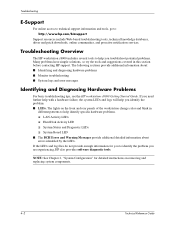
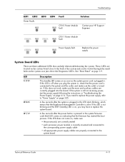
...LED ❏ System Status and Diagnostic LEDs ❏ System Board LED ■ The BCH Error and Warning Messages provide additional detailed information about : ■ Identifying and diagnosing hardware problems ■ Monitor troubleshooting ■ System logs and error messages Identifying and Diagnosing Hardware Problems For basic troubleshooting tips, see the HP workstation c8000... Getting Started Guide. The lights on removing and replacing system components. 4-2 Technical Reference Guide If the LEDs and log files do not ...
...LED ❏ System Status and Diagnostic LEDs ❏ System Board LED ■ The BCH Error and Warning Messages provide additional detailed information about : ■ Identifying and diagnosing hardware problems ■ Monitor troubleshooting ■ System logs and error messages Identifying and Diagnosing Hardware Problems For basic troubleshooting tips, see the HP workstation c8000... Getting Started Guide. The lights on removing and replacing system components. 4-2 Technical Reference Guide If the LEDs and log files do not ...
HP Workstation c8000 Technical Reference Guide
Page 74
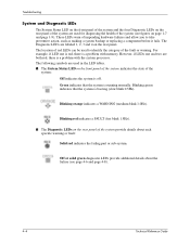
... indicates the system is running normally. Green indicates that the system is a problem with the system processor. Off or solid green diagnostic LEDs provide additional details about each specific warning or fault: Solid red indicates the failing part or sub-system. For example, if... you to identify the category of the fault or warning. The Diagnostic LEDs are labeled 1, 2, 3 and 4 on the rear panel. Troubleshooting System and Diagnostic LEDs The System Status LED on the front panel of the system and the four Diagnostic LEDs on the rear panel of the system are used for diagnosing the...
... indicates the system is running normally. Green indicates that the system is a problem with the system processor. Off or solid green diagnostic LEDs provide additional details about each specific warning or fault: Solid red indicates the failing part or sub-system. For example, if... you to identify the category of the fault or warning. The Diagnostic LEDs are labeled 1, 2, 3 and 4 on the rear panel. Troubleshooting System and Diagnostic LEDs The System Status LED on the front panel of the system and the four Diagnostic LEDs on the rear panel of the system are used for diagnosing the...
HP Workstation c8000 Technical Reference Guide
Page 76
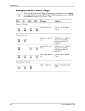
Memory Warnings Mismatched memory pairs. Can't detect memory Contact your HP Support Engineer. LED1 LED2 LED3 Unknown Warnings LED4 Warning Unknown warning. Replace the system board battery. 4-6 Technical Reference Guide ... Warnings Battery voltage low. Memory load order error. Troubleshooting Warnings (System LED is Blinking Orange) The following tables provide additional information about each specific warning associated with the various possible Diagnostic LED lighting sequences when the system LED is orange (medium blink 1.0Hz). Use the memory sequence diagram in...
Memory Warnings Mismatched memory pairs. Can't detect memory Contact your HP Support Engineer. LED1 LED2 LED3 Unknown Warnings LED4 Warning Unknown warning. Replace the system board battery. 4-6 Technical Reference Guide ... Warnings Battery voltage low. Memory load order error. Troubleshooting Warnings (System LED is Blinking Orange) The following tables provide additional information about each specific warning associated with the various possible Diagnostic LED lighting sequences when the system LED is orange (medium blink 1.0Hz). Use the memory sequence diagram in...
HP Workstation c8000 Technical Reference Guide
Page 78
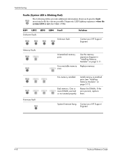
...Blinking Red) The following tables provide additional information about each specific fault associated with the various possible Diagnostic LED lighting sequences when the system LED is red (fast blink 1.5Hz). Uncorrectable memory error. Use the memory sequence diagram in matched pairs... (see "Installing Memory Modules" on page 3-11. Memory Faults Mismatched memory pairs. Solution Contact your HP Support Engineer. 4-8 Technical Reference Guide Contact your HP ...
...Blinking Red) The following tables provide additional information about each specific fault associated with the various possible Diagnostic LED lighting sequences when the system LED is red (fast blink 1.5Hz). Uncorrectable memory error. Use the memory sequence diagram in matched pairs... (see "Installing Memory Modules" on page 3-11. Memory Faults Mismatched memory pairs. Solution Contact your HP Support Engineer. 4-8 Technical Reference Guide Contact your HP ...
HP Workstation c8000 Technical Reference Guide
Page 81
... plugged in "Troubleshooting the Power Supply" on indicating that can be viewed through the small holes in the system case just above the Diagnostic LEDs. A few seconds after the power button is on page 3-25. Contact your HP Support Engineer. Troubleshooting LED1 LED2 Power Faults LED3 LED4 Fault Solution CPU 0 Power Module fault...
... plugged in "Troubleshooting the Power Supply" on indicating that can be viewed through the small holes in the system case just above the Diagnostic LEDs. A few seconds after the power button is on page 3-25. Contact your HP Support Engineer. Troubleshooting LED1 LED2 Power Faults LED3 LED4 Fault Solution CPU 0 Power Module fault...

HP Workstation c8000 Technical Reference Guide
Page 85
...HP Offline Diagnostics Environment CD: 1. Depending on your HP system. Select View Release Notes and Documentation Menu. 2. NOTE: If you run ODE from the ODE Main Menu: 1. These tools may include some types of tools provided on your system and configuration, these may be ignored: they do not apply to c8000... CD then will boot to boot from the launch menu. To run the HP diagnostic software, note any LED error messages. Offline Diagnostics Environment (ODE) The Offline Diagnostics Environment is an offline support tools platform that enables users to troubleshoot a system...
...HP Offline Diagnostics Environment CD: 1. Depending on your HP system. Select View Release Notes and Documentation Menu. 2. NOTE: If you run ODE from the ODE Main Menu: 1. These tools may include some types of tools provided on your system and configuration, these may be ignored: they do not apply to c8000... CD then will boot to boot from the launch menu. To run the HP diagnostic software, note any LED error messages. Offline Diagnostics Environment (ODE) The Offline Diagnostics Environment is an offline support tools platform that enables users to troubleshoot a system...

HP Workstation c8000 Technical Reference Guide
Page 113
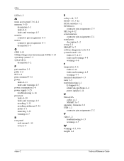
...CD-ROM jumpers A-7 components 3-7 configuration 2-1 connectors pin assignments C-1 rear panel, rack-mount 1-10 rear panel, tower 1-9 D diagnostics 4-2 dimensions 1-4 DIMMs 3-10 drive device designation A-1 replacement type A-6 DVD-ROM jumpers A-7 E environmental specificaions 1-6 E-Support 4-2 Ethernet... rack-mount 1-8 tower 1-7 G graphics troubleshooting 4-13 warnings 4-7 graphics controller 1-2 H hard drive 3-19 description 1-1 paths 2-2 hard drive activity LED 3-21, 4-3 humidity 1-6 I I/O connectors 1-2 IDE 2-2, 3-17, 3-19 cables 3-18 connector pin assignments C-6 controller 1-2 J jumpers CD-...
...CD-ROM jumpers A-7 components 3-7 configuration 2-1 connectors pin assignments C-1 rear panel, rack-mount 1-10 rear panel, tower 1-9 D diagnostics 4-2 dimensions 1-4 DIMMs 3-10 drive device designation A-1 replacement type A-6 DVD-ROM jumpers A-7 E environmental specificaions 1-6 E-Support 4-2 Ethernet... rack-mount 1-8 tower 1-7 G graphics troubleshooting 4-13 warnings 4-7 graphics controller 1-2 H hard drive 3-19 description 1-1 paths 2-2 hard drive activity LED 3-21, 4-3 humidity 1-6 I I/O connectors 1-2 IDE 2-2, 3-17, 3-19 cables 3-18 connector pin assignments C-6 controller 1-2 J jumpers CD-...
HP Workstation c8000 Technical Reference Guide
Page 114
Index LEDs 4-3 M main access panel 3-6, 4-1 memory 3-10 description 1-1 faults 4-8 faults and warnings 4-5 monitor connector pin assignments C-4 mouse connector pin assignments C-1 description 1-3 O ODE 4-15 Offline Diagnostics Environment (ODE) 4-15 operating system 1-1 optical drive description 1-2...drives connector pin assignments C-3 SEL log 4-12 serial interface connector pin assignments C-1 serial ports description 1-2 set-up 2-1 SMART A-7 software diagnostic tools 4-2 system board 3-39 faults 4-9, 4-11 faults and warnings 4-5 warnings 4-6 T temperature 1-6 faults 4-10 faults and warnings ...
Index LEDs 4-3 M main access panel 3-6, 4-1 memory 3-10 description 1-1 faults 4-8 faults and warnings 4-5 monitor connector pin assignments C-4 mouse connector pin assignments C-1 description 1-3 O ODE 4-15 Offline Diagnostics Environment (ODE) 4-15 operating system 1-1 optical drive description 1-2...drives connector pin assignments C-3 SEL log 4-12 serial interface connector pin assignments C-1 serial ports description 1-2 set-up 2-1 SMART A-7 software diagnostic tools 4-2 system board 3-39 faults 4-9, 4-11 faults and warnings 4-5 warnings 4-6 T temperature 1-6 faults 4-10 faults and warnings ...

HP Workstation c8000 Getting Started Guide
Page 3
... 4-2 System Does Not Start Properly 4-2 Keyboard Problems 4-3 Mouse Problems 4-4 Monitor Remains Blank When System is On 4-5 You Forgot the BCH Password(s 4-5 Troubleshooting with the System LEDs 4-6 System Event Log 4-8 Software Diagnostics Tools 4-9 Offline Diagnostics Environment 4-9 Recovering the OS 4-10 HP workstation c8000 -
... 4-2 System Does Not Start Properly 4-2 Keyboard Problems 4-3 Mouse Problems 4-4 Monitor Remains Blank When System is On 4-5 You Forgot the BCH Password(s 4-5 Troubleshooting with the System LEDs 4-6 System Event Log 4-8 Software Diagnostics Tools 4-9 Offline Diagnostics Environment 4-9 Recovering the OS 4-10 HP workstation c8000 -

HP Workstation c8000 Getting Started Guide
Page 15
Diagnostic LEDs 5 Security cable slot q Transfer-of-control (TOC) button 6 Monitor connector (on graphics card) HP workstation c8000 - bottom connector is serial port A; Getting Started 1-7 Hardware Setup Rear Panel Features The HP workstation c8000 rear panel has the following connectors and features: Rear panel, tower configuration 1 Power supply LED (inside power supply) 7 LAN connector and LEDs 2 Power cord connector 8 Three USB connectors 3 PCI/AGP retention release 9 Two serial connectors (top connector is serial port B) 4 External SCSI connector (option) -
Diagnostic LEDs 5 Security cable slot q Transfer-of-control (TOC) button 6 Monitor connector (on graphics card) HP workstation c8000 - bottom connector is serial port A; Getting Started 1-7 Hardware Setup Rear Panel Features The HP workstation c8000 rear panel has the following connectors and features: Rear panel, tower configuration 1 Power supply LED (inside power supply) 7 LAN connector and LEDs 2 Power cord connector 8 Three USB connectors 3 PCI/AGP retention release 9 Two serial connectors (top connector is serial port B) 4 External SCSI connector (option) -

HP Workstation c8000 Getting Started Guide
Page 16
Hardware Setup Rear panel, rack-mount configuration 1 Power supply LED (inside power supply) 7 LAN connector and LEDs 2 Power cord connector 8 Three USB connectors 3 PCI/AGP retention release 9 Two serial connectors (left connector is serial port B) 4 External SCSI connector (option) - Getting Started right connector is serial port A; Diagnostic LEDs 5 Security cable slot q Transfer-of-control (TOC) button 6 Monitor connector (on graphics card) 1-8 HP workstation c8000 -
Hardware Setup Rear panel, rack-mount configuration 1 Power supply LED (inside power supply) 7 LAN connector and LEDs 2 Power cord connector 8 Three USB connectors 3 PCI/AGP retention release 9 Two serial connectors (left connector is serial port B) 4 External SCSI connector (option) - Getting Started right connector is serial port A; Diagnostic LEDs 5 Security cable slot q Transfer-of-control (TOC) button 6 Monitor connector (on graphics card) 1-8 HP workstation c8000 -
HP Workstation c8000 Getting Started Guide
Page 18
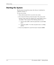
Press the power button on the rear panel create a scrolling pattern. 3. The system starts. Diagnostic LEDs 1-4 on the front panel. This is initialized as explained on and blinks green. b. The following should occur: a. If you are prompted for up to ...on the monitor before you start your system: 1. Getting Started During system startup, the display may remain blank for a password, type it and press Enter. 2-2 HP workstation c8000 - To start your system. 2. Software Setup Starting the System The first time you start the system, the software is normal. System status...
Press the power button on the rear panel create a scrolling pattern. 3. The system starts. Diagnostic LEDs 1-4 on the front panel. This is initialized as explained on and blinks green. b. The following should occur: a. If you are prompted for up to ...on the monitor before you start your system: 1. Getting Started During system startup, the display may remain blank for a password, type it and press Enter. 2-2 HP workstation c8000 - To start your system. 2. Software Setup Starting the System The first time you start the system, the software is normal. System status...
HP Workstation c8000 Getting Started Guide
Page 32
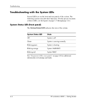
... is booting Blinking orange System WARNING Blinking red System FAULT See "Diagnostic LEDs (rear panel)" on page 4-8 for additional information on the front and rear panels of the system. Getting Started Troubleshooting Troubleshooting with the System LEDs Several LEDs are on warnings and faults. 4-6 HP workstation c8000 - The following sections describe their functions. (For the precise locations...
... is booting Blinking orange System WARNING Blinking red System FAULT See "Diagnostic LEDs (rear panel)" on page 4-8 for additional information on the front and rear panels of the system. Getting Started Troubleshooting Troubleshooting with the System LEDs Several LEDs are on warnings and faults. 4-6 HP workstation c8000 - The following sections describe their functions. (For the precise locations...
HP Workstation c8000 Getting Started Guide
Page 34
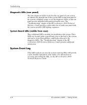
... error, the system event log (SEL) will provide a more detailed explanation of the HP workstation c8000 Technical Reference Guide provides additional information. For information on the rear panel provide additional information about the error. Troubleshooting Diagnostic LEDs (rear panel) The four diagnostic LEDs located on the rear panel of your system are located on the system board...
... error, the system event log (SEL) will provide a more detailed explanation of the HP workstation c8000 Technical Reference Guide provides additional information. For information on the rear panel provide additional information about the error. Troubleshooting Diagnostic LEDs (rear panel) The four diagnostic LEDs located on the rear panel of your system are located on the system board...
HP Workstation c8000 Getting Started Guide
Page 35
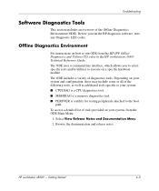
... to the HP workstation c8000 Technical Reference Guide. Getting Started 4-9 Troubleshooting Software Diagnostics Tools This section includes an overview of diagnostics tools. HP workstation c8000 - To access a detailed list of the following tools, as well as additional tools specific to your system, from the HP IPF Offline Diagnostics and Utilities CD, refer to run the HP diagnostic software, note any Diagnostic LED codes. Before...
... to the HP workstation c8000 Technical Reference Guide. Getting Started 4-9 Troubleshooting Software Diagnostics Tools This section includes an overview of diagnostics tools. HP workstation c8000 - To access a detailed list of the following tools, as well as additional tools specific to your system, from the HP IPF Offline Diagnostics and Utilities CD, refer to run the HP diagnostic software, note any Diagnostic LED codes. Before...


