HP Color LaserJet 2605/2605dn/2605dtn - Software Technical Reference
Page 302
...the fuser. Paper which has just gone through the fuser before being printed on the duplex side is worst for the duplex side. The HP ToolboxFX algorithm increases or decreases the current temperature target by some amount which depends on media type and other factors. When the paper reabsorbs...transfer bias voltage in transfer bias means that sticks to the fuser sleeve gets too hot and partially separates from contact with the OPC drum by their surface area spaced away from the toner that the transfer control algorithm increases or decreases the transfer bias by some amount which...
...the fuser. Paper which has just gone through the fuser before being printed on the duplex side is worst for the duplex side. The HP ToolboxFX algorithm increases or decreases the current temperature target by some amount which depends on media type and other factors. When the paper reabsorbs...transfer bias voltage in transfer bias means that sticks to the fuser sleeve gets too hot and partially separates from contact with the OPC drum by their surface area spaced away from the toner that the transfer control algorithm increases or decreases the transfer bias by some amount which...
HP Color LaserJet 2605/2605dn/2605dtn - Software Technical Reference
Page 303
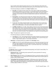
... This setting increases transfer current. The following settings are available for fixing toner scatter on the engine's internal tables. The HP Color LaserJet 2605 series printer has an electrostatic discharge brush right where the paper separates from the ETB (before and after pages are applied to help find... Rough papers such as cotton bond papers have good transfer, the transfer bias voltage needs to leave a conductive residue on the OPC drums. The On setting turns on increased OPC/ETB cleaning rotations before the fuser). In this residue. ● Trailing Edge Over-development ...
... This setting increases transfer current. The following settings are available for fixing toner scatter on the engine's internal tables. The HP Color LaserJet 2605 series printer has an electrostatic discharge brush right where the paper separates from the ETB (before and after pages are applied to help find... Rough papers such as cotton bond papers have good transfer, the transfer bias voltage needs to leave a conductive residue on the OPC drums. The On setting turns on increased OPC/ETB cleaning rotations before the fuser). In this residue. ● Trailing Edge Over-development ...

HP Color LaserJet 2605/2605dn/2605dtn - Software Technical Reference
Page 360
... Settings tab 173 Device Status page, HP EWS 312 Device Status screen, HP ToolboxFX 250 Device Support area, HP Solution Center 37 dialog boxes, Macintosh installation 58 dialog boxes, Microsoft Windows installation Cancel 101 Check Printer Connection 92 Confirm Settings 95 Congratulations 100... level 3 emulation support 132 HP postscript level 3 emulation support 232 localized versions 18, 51 Macintosh 50 network installation, Microsoft Windows 76 Plug and Play installation 66 Windows 15 Drum low threshold settings 281 duplexing paper specifications 311 PCL 6 traditional driver settings 192 ...
... Settings tab 173 Device Status page, HP EWS 312 Device Status screen, HP ToolboxFX 250 Device Support area, HP Solution Center 37 dialog boxes, Macintosh installation 58 dialog boxes, Microsoft Windows installation Cancel 101 Check Printer Connection 92 Confirm Settings 95 Congratulations 100... level 3 emulation support 132 HP postscript level 3 emulation support 232 localized versions 18, 51 Macintosh 50 network installation, Microsoft Windows 76 Plug and Play installation 66 Windows 15 Drum low threshold settings 281 duplexing paper specifications 311 PCL 6 traditional driver settings 192 ...

Service Manual
Page 66
... the end of WAIT or LSTR until the end To clear the drum surface of print command from the formatter. To form the image on the photosensitive drum based on . Also used to print. The printer enters INTR after the completion of LSTR until power-off until the ...until the developing high-voltage is off. potential and to transfer the toner image onto paper. To stablize the photosensitive drum sensitivity for a detailed timing chart. It drives the laser/scanner system, the image formation system, and the pickup and feed system. The engine control system contains the following...
... the end of WAIT or LSTR until the end To clear the drum surface of print command from the formatter. To form the image on the photosensitive drum based on . Also used to print. The printer enters INTR after the completion of LSTR until power-off until the ...until the developing high-voltage is off. potential and to transfer the toner image onto paper. To stablize the photosensitive drum sensitivity for a detailed timing chart. It drives the laser/scanner system, the image formation system, and the pickup and feed system. The engine control system contains the following...

Service Manual
Page 68
... of rotation CW CW/CCW CW - Table 4-2 Motor specifications Name Motor Purpose Type Main motor (M1) Drive ETB belt, photosensitive drum and developing cylinder DC motor Fuser/delivery motor (M2) Drive fuser pressure roller, delivery roller and automatic release of fuser pressure Stepping motor...the following condition. Failure detection Yes No No Yes Main motor failure detection The CPU determines the main motor failure, stops the printer, and notifies the formatter of the /MAINMFG signal stays at an irregular interval for approximately 10 seconds and longer during fan motor...
... of rotation CW CW/CCW CW - Table 4-2 Motor specifications Name Motor Purpose Type Main motor (M1) Drive ETB belt, photosensitive drum and developing cylinder DC motor Fuser/delivery motor (M2) Drive fuser pressure roller, delivery roller and automatic release of fuser pressure Stepping motor...the following condition. Failure detection Yes No No Yes Main motor failure detection The CPU determines the main motor failure, stops the printer, and notifies the formatter of the /MAINMFG signal stays at an irregular interval for approximately 10 seconds and longer during fan motor...

Service Manual
Page 72
... a negative electrical charge remains in the unexposed drum surface area by applying toner. Step 6: Fuser 5. Electrostatic latent image formation stage Forms an electrostatic latent image on the photosensitive drum. Step 1: Primary charging Step 2: Laser beam exposure 2. The principal process of image formation... is removed from the exposed area. Fuser stage Fuses the toner image on the drum is called an "electrostatic latent image...
... a negative electrical charge remains in the unexposed drum surface area by applying toner. Step 6: Fuser 5. Electrostatic latent image formation stage Forms an electrostatic latent image on the photosensitive drum. Step 1: Primary charging Step 2: Laser beam exposure 2. The principal process of image formation... is removed from the exposed area. Fuser stage Fuses the toner image on the drum is called an "electrostatic latent image...

Service Manual
Page 73
.... Figure 4-4 Latent image formation Laser/scanner system The laser/scanner system forms latent images on the photosensitive drum surface is visualized by the non-magnetic, singlecomponent toner. Figure 4-5 Laser beam exposure Developing stage The electrostatic latent image on the photosensitive drum according to the VIDEO signals sent from the formatter. This printer utilizes the projection development...
.... Figure 4-4 Latent image formation Laser/scanner system The laser/scanner system forms latent images on the photosensitive drum surface is visualized by the non-magnetic, singlecomponent toner. Figure 4-5 Laser beam exposure Developing stage The electrostatic latent image on the photosensitive drum according to the VIDEO signals sent from the formatter. This printer utilizes the projection development...

Service Manual
Page 74
...four print cartridges: magenta (M), cyan (C), yellow (Y), and black (K). 64 Chapter 4 Operational theory ENWW The area of the photosensitive drum, where the laser beam is exposed, has higher potential than the toner, which is called the projection development and it visualizes the electrostatic latent image on... the drum. This printer is applied the AC bias in order to changes of the output image. Figure 4-6 Developing stage...
...four print cartridges: magenta (M), cyan (C), yellow (Y), and black (K). 64 Chapter 4 Operational theory ENWW The area of the photosensitive drum, where the laser beam is exposed, has higher potential than the toner, which is called the projection development and it visualizes the electrostatic latent image on... the drum. This printer is applied the AC bias in order to changes of the output image. Figure 4-6 Developing stage...

Service Manual
Page 75
During printing, the picked up paper is conveyed in between the ETB and the photosensitive drum, and simultaneously the toner image is read in the color misregistration/density sensor unit. ENWW Image formation system 65 This pattern image is transferred onto the paper. The transfer...rotates the ETB feed roller, the ETB feed roller rotates the ETB belt. The pattern image for the color misregistration or image density determination is also used for color misregistration corrective control and the image stabilization control. Figure 4-7 Print cartridge structure Transfer belt (ETB) The ...
During printing, the picked up paper is conveyed in between the ETB and the photosensitive drum, and simultaneously the toner image is read in the color misregistration/density sensor unit. ENWW Image formation system 65 This pattern image is transferred onto the paper. The transfer...rotates the ETB feed roller, the ETB feed roller rotates the ETB belt. The pattern image for the color misregistration or image density determination is also used for color misregistration corrective control and the image stabilization control. Figure 4-7 Print cartridge structure Transfer belt (ETB) The ...

Service Manual
Page 76
Figure 4-9 Transfer stage 66 Chapter 4 Operational theory ENWW Figure 4-8 ETB unit Transfer stage The transfer stage is to transfer the toner image on the photosensitive drum surface onto paper.
Figure 4-9 Transfer stage 66 Chapter 4 Operational theory ENWW Figure 4-8 ETB unit Transfer stage The transfer stage is to transfer the toner image on the photosensitive drum surface onto paper.

Service Manual
Page 77
...the back side of the paper. In the fusing stage, the printer used heat and pressure to the positive charge from the drum by using the on-demand fuser method in this step. The toner on the photosensitive drum surface is transferred onto the paper according to make the image permanent.... The printer applies the DC positive bias to the paper by the static electricity. Each color's toner image is fused onto the paper by its elasticity (...
...the back side of the paper. In the fusing stage, the printer used heat and pressure to the positive charge from the drum by using the on-demand fuser method in this step. The toner on the photosensitive drum surface is transferred onto the paper according to make the image permanent.... The printer applies the DC positive bias to the paper by the static electricity. Each color's toner image is fused onto the paper by its elasticity (...

Service Manual
Page 81
...fuser. Paper skew is corrected by the registration shutter when the paper is fed to the paper from the photosensitive drum and then the paper is fed into the printer is the operational sequence of the registration roller. Toner is transfered to the fuser/delivery stage. Skew correction by ... by the single-sheet priority feed slot paper sensor (SR3). When the paper is fed by the registration shutter If the paper fed into the printer. 2. Instead of a pickup roller, the registration roller picks up one sheet of paper only that is detected by the registration roller. 3. After...
...fuser. Paper skew is corrected by the registration shutter when the paper is fed to the paper from the photosensitive drum and then the paper is fed into the printer is the operational sequence of the registration roller. Toner is transfered to the fuser/delivery stage. Skew correction by ... by the single-sheet priority feed slot paper sensor (SR3). When the paper is fed by the registration shutter If the paper fed into the printer. 2. Instead of a pickup roller, the registration roller picks up one sheet of paper only that is detected by the registration roller. 3. After...

Service Manual
Page 178
...55.1000 57.0000 57.0001 59.0000 59.0001 101.0000 102.0000 103.0000 Description Paper jam, registration drum area Paper jam, drum fuser area Paper jam, fuser output area Memory out Video under run Low temperature fuser error Slow fuser error ...failure Fuser high temperature subtherm failure Scanner error, black laser failure Scanner error, cyan laser failure Scanner error, magenta laser failure Scanner error, yellow laser failure Density sensor error Color plane registration sensor error Sensor density contaminated Sensor color plane registration contaminated Engine comm fatal error Engine comm ...
...55.1000 57.0000 57.0001 59.0000 59.0001 101.0000 102.0000 103.0000 Description Paper jam, registration drum area Paper jam, drum fuser area Paper jam, fuser output area Memory out Video under run Low temperature fuser error Slow fuser error ...failure Fuser high temperature subtherm failure Scanner error, black laser failure Scanner error, cyan laser failure Scanner error, magenta laser failure Scanner error, yellow laser failure Density sensor error Color plane registration sensor error Sensor density contaminated Sensor color plane registration contaminated Engine comm fatal error Engine comm ...


