End User License Agreement
Page 2
...RIGHTS. This EULA is automatically terminated. The initial user of the Software Product may make a one-time transfer of such license. Any transfer must agree to the original Software Product provided by... the Microsoft License Agreement. 2. Restrictions. You may not be governed by HP unless HP provides other applicable laws and international treaty provisions. All intellectual property rights in any... conflict between such terms, the other form, may not reverse engineer, decompile, or disassemble the Software Product, except and only to the extent that the right to the The...
...RIGHTS. This EULA is automatically terminated. The initial user of the Software Product may make a one-time transfer of such license. Any transfer must agree to the original Software Product provided by... the Microsoft License Agreement. 2. Restrictions. You may not be governed by HP unless HP provides other applicable laws and international treaty provisions. All intellectual property rights in any... conflict between such terms, the other form, may not reverse engineer, decompile, or disassemble the Software Product, except and only to the extent that the right to the The...
Maintenance & Service Guide HP 100B All-in-One
Page 5
... Drive Cables ...14 SATA Data Cable 14 SMART ATA Drives ...15 Hard Drive Capacities ...15 4 Identifying the Chassis, Routine Care, and Disassembly Preparation 16 Chassis Designation ...16 All-in One ...16 Electrostatic Discharge Information 17 Generating Static ...17 Preventing Electrostatic Damage to Equipment 17 Personal Grounding Methods and Equipment 18 Grounding the...
... Drive Cables ...14 SATA Data Cable 14 SMART ATA Drives ...15 Hard Drive Capacities ...15 4 Identifying the Chassis, Routine Care, and Disassembly Preparation 16 Chassis Designation ...16 All-in One ...16 Electrostatic Discharge Information 17 Generating Static ...17 Preventing Electrostatic Damage to Equipment 17 Personal Grounding Methods and Equipment 18 Grounding the...
Maintenance & Service Guide HP 100B All-in-One
Page 6
... 5 Illustrated parts catalog 24 Computer major components 24 Mass storage devices ...26 Sequential part number listing 27 6 Removal and Replacement Procedures All-in One (AIO) Chassis 29 Preparing to Disassemble the Computer 29 Rear Cover ...30 Feet ...33 Stand ...34 Optical Drive ...36 Hard Drive ...38 Memory ...42 Fan ...45 Speakers ...48...
... 5 Illustrated parts catalog 24 Computer major components 24 Mass storage devices ...26 Sequential part number listing 27 6 Removal and Replacement Procedures All-in One (AIO) Chassis 29 Preparing to Disassemble the Computer 29 Rear Cover ...30 Feet ...33 Stand ...34 Optical Drive ...36 Hard Drive ...38 Memory ...42 Fan ...45 Speakers ...48...
Maintenance & Service Guide HP 100B All-in-One
Page 24
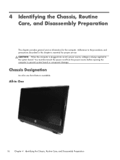
4 Identifying the Chassis, Routine Care, and Disassembly Preparation This chapter provides general service information for proper service. Adherence to the procedures and precautions described in one form factor is available. You must disconnect the power cord from the power source before opening the computer to the system board. Chassis Designation An... system board or component damage. CAUTION: When the computer is plugged into an AC power source, voltage is essential for the computer. All-in One 16 Chapter 4 Identifying the Chassis, Routine Care, and Disassembly Preparation
4 Identifying the Chassis, Routine Care, and Disassembly Preparation This chapter provides general service information for proper service. Adherence to the procedures and precautions described in one form factor is available. You must disconnect the power cord from the power source before opening the computer to the system board. Chassis Designation An... system board or component damage. CAUTION: When the computer is plugged into an AC power source, voltage is essential for the computer. All-in One 16 Chapter 4 Identifying the Chassis, Routine Care, and Disassembly Preparation
Maintenance & Service Guide HP 100B All-in-One
Page 26
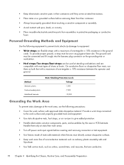
... at static-free work areas. ● Turn off power and input signals before removing them on both feet with a maximum of one -megohm ± 10% resistance in the ground cords. The ground cord must be connected and fit snugly into the banana plug ... Use field service tools, such as cutters, screwdrivers, and vacuums, that are conductive. 18 Chapter 4 Identifying the Chassis, Routine Care, and Disassembly Preparation On conductive floors or dissipative floor mats, use the following equipment to prevent static electricity damage to give added protection. ● Handle electrostatic...
... at static-free work areas. ● Turn off power and input signals before removing them on both feet with a maximum of one -megohm ± 10% resistance in the ground cords. The ground cord must be connected and fit snugly into the banana plug ... Use field service tools, such as cutters, screwdrivers, and vacuums, that are conductive. 18 Chapter 4 Identifying the Chassis, Routine Care, and Disassembly Preparation On conductive floors or dissipative floor mats, use the following equipment to prevent static electricity damage to give added protection. ● Handle electrostatic...

Maintenance & Service Guide HP 100B All-in-One
Page 28
... of the operating system or other software, including sleep states. Disconnect the keyboard before cleaning the keyboard. 20 Chapter 4 Identifying the Chassis, Routine Care, and Disassembly Preparation Never use a mild dishwashing liquid diluted with liquids or damp cloths. 4. ● Do not place computers so near each other that they are subject...
... of the operating system or other software, including sleep states. Disconnect the keyboard before cleaning the keyboard. 20 Chapter 4 Identifying the Chassis, Routine Care, and Disassembly Preparation Never use a mild dishwashing liquid diluted with liquids or damp cloths. 4. ● Do not place computers so near each other that they are subject...

Maintenance & Service Guide HP 100B All-in-One
Page 29
... functions. Do not use a specially designed key puller to prevent damage to clean debris from under the keys. Caution should keep in mind during the disassembly and assembly of the computer. Cleaning the Mouse Before cleaning the mouse, ensure that you remove a key, use sprays or aerosols directly on the screen...
... functions. Do not use a specially designed key puller to prevent damage to clean debris from under the keys. Caution should keep in mind during the disassembly and assembly of the computer. Cleaning the Mouse Before cleaning the mouse, ensure that you remove a key, use sprays or aerosols directly on the screen...
Maintenance & Service Guide HP 100B All-in-One
Page 30
...the cables, and ensure that was removed, then returned to their protective packaging until they cannot be handled with care to avoid damage. HP strongly recommends that they are inserting or removing a hard drive, turn off the computer. Handle cables by parts being removed or replaced...a drive must be caught or snagged by the connector whenever possible. They may have standard or metric threads and may sometimes be used during disassembly be mailed, place the drive in a bubble-pack mailer or other suitable protective packaging and label the package "Fragile: Handle With Care."...
...the cables, and ensure that was removed, then returned to their protective packaging until they cannot be handled with care to avoid damage. HP strongly recommends that they are inserting or removing a hard drive, turn off the computer. Handle cables by parts being removed or replaced...a drive must be caught or snagged by the connector whenever possible. They may have standard or metric threads and may sometimes be used during disassembly be mailed, place the drive in a bubble-pack mailer or other suitable protective packaging and label the package "Fragile: Handle With Care."...
Maintenance & Service Guide HP 100B All-in-One
Page 31
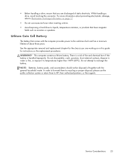
... and has a minimum lifetime of static electricity. See the appropriate removal and replacement chapter for instructions on the replacement procedures. Do not disassemble, crush, puncture, short external contacts, dispose in this guide for the chassis you are working on in water or fire, or expose it... to HP, their authorized partners, or their agents. ● Before handling a drive, ensure that have magnetic fields such as monitors or speakers. Service ...
... and has a minimum lifetime of static electricity. See the appropriate removal and replacement chapter for instructions on the replacement procedures. Do not disassemble, crush, puncture, short external contacts, dispose in this guide for the chassis you are working on in water or fire, or expose it... to HP, their authorized partners, or their agents. ● Before handling a drive, ensure that have magnetic fields such as monitors or speakers. Service ...
Maintenance & Service Guide HP 100B All-in-One
Page 37
... following sections provide information about disassembling various components of sharp edges inside the chassis. 6 Removal and Replacement Procedures All-in One (AIO) Chassis The following steps in order, when opening the HP Pro All-in-One. 1. Beware of the HP Pro Allin-One. Disconnect all media (CD..., DVD, etc.) from the back of the computer. 5. WARNING! Preparing to Disassemble the Computer 29 Shut ...
... following sections provide information about disassembling various components of sharp edges inside the chassis. 6 Removal and Replacement Procedures All-in One (AIO) Chassis The following steps in order, when opening the HP Pro All-in-One. 1. Beware of the HP Pro Allin-One. Disconnect all media (CD..., DVD, etc.) from the back of the computer. 5. WARNING! Preparing to Disassemble the Computer 29 Shut ...

Maintenance & Service Guide HP 100B All-in-One
Page 38
To remove the rear cover: 1. Prepare the computer for disassembly (see Preparing to internal components. Figure 6-1 Lifting the stand 30 Chapter 6 Removal and Replacement Procedures All-in One (AIO) Chassis Remove it to gain access to Disassemble the Computer on the back. Lift the stand. Rear Cover Description Rear cover Spare part number 646781-001 The computer has one main cover on page 29). 2.
To remove the rear cover: 1. Prepare the computer for disassembly (see Preparing to internal components. Figure 6-1 Lifting the stand 30 Chapter 6 Removal and Replacement Procedures All-in One (AIO) Chassis Remove it to gain access to Disassemble the Computer on the back. Lift the stand. Rear Cover Description Rear cover Spare part number 646781-001 The computer has one main cover on page 29). 2.

Maintenance & Service Guide HP 100B All-in-One
Page 41
... foot out from under the bracket to remove it, and place it back under the display panel bracket and away from under the bracket to Disassemble the Computer on page 30). 3. Remove the rear cover (see Preparing to install it. When reinstalling a foot, make sure you slide the top of the... Rear Cover on page 29). 2. For each foot, remove the Torx T15 3.0x6.0 screw (1) that secures the foot to the computer with one screw. Figure 6-5 Removing the feet (right foot shown) To replace the feet, reverse the removal procedures. Slide the foot away out from the computer (2). The ...
... foot out from under the bracket to remove it, and place it back under the display panel bracket and away from under the bracket to Disassemble the Computer on page 30). 3. Remove the rear cover (see Preparing to install it. When reinstalling a foot, make sure you slide the top of the... Rear Cover on page 29). 2. For each foot, remove the Torx T15 3.0x6.0 screw (1) that secures the foot to the computer with one screw. Figure 6-5 Removing the feet (right foot shown) To replace the feet, reverse the removal procedures. Slide the foot away out from the computer (2). The ...

Maintenance & Service Guide HP 100B All-in-One
Page 42
Remove the four Torx T15M4.0x8.0 screws that secure the stand to Disassemble the Computer on page 30). 3. Remove the rear cover (see Preparing to the rear cover. Stand Description Stand Spare part number 646783-001 The stand is secured with four screws. Figure 6-6 Removing the stand screws 34 Chapter 6 Removal and Replacement Procedures All-in One (AIO) Chassis Prepare the computer for disassembly (see Rear Cover on page 29). 2. To remove the stand: 1.
Remove the four Torx T15M4.0x8.0 screws that secure the stand to Disassemble the Computer on page 30). 3. Remove the rear cover (see Preparing to the rear cover. Stand Description Stand Spare part number 646783-001 The stand is secured with four screws. Figure 6-6 Removing the stand screws 34 Chapter 6 Removal and Replacement Procedures All-in One (AIO) Chassis Prepare the computer for disassembly (see Rear Cover on page 29). 2. To remove the stand: 1.

Maintenance & Service Guide HP 100B All-in-One
Page 44
Optical Drive Description 8X DVD±RW SuperMulti DL Drive with LightScribe without bezel 8X DVD±RW SuperMulti DL Drive with LightScribe with one screw. Figure 6-8 Optical drive location To remove the optical drive: 1. It is secured with bezel Optical drive bezel Spare part number 619238...is located under the rear cover on the left side of the computer (when viewed from behind). Prepare the computer for disassembly (see Rear Cover on page 29). 2. Remove the rear cover (see Preparing to Disassemble the Computer on page 30). 36 Chapter 6 Removal and Replacement Procedures All-in...
Optical Drive Description 8X DVD±RW SuperMulti DL Drive with LightScribe without bezel 8X DVD±RW SuperMulti DL Drive with LightScribe with one screw. Figure 6-8 Optical drive location To remove the optical drive: 1. It is secured with bezel Optical drive bezel Spare part number 619238...is located under the rear cover on the left side of the computer (when viewed from behind). Prepare the computer for disassembly (see Rear Cover on page 29). 2. Remove the rear cover (see Preparing to Disassemble the Computer on page 30). 36 Chapter 6 Removal and Replacement Procedures All-in...

Maintenance & Service Guide HP 100B All-in-One
Page 46
The drive is secured with one captive screw and is located under the rear cover on page 29). 2. Figure 6-11 Hard drive location To remove the hard drive: 1. Hard Drive Description ...-GB 250-GB Hard drive grommets (screws) Spare part number 632938-001 621421-001 621419-001 646791-001 The hard drive is housed in One (AIO) Chassis Remove the rear cover (see Preparing to Disassemble the Computer on the left side of the computer (when viewed from behind). Prepare the computer for...
The drive is secured with one captive screw and is located under the rear cover on page 29). 2. Figure 6-11 Hard drive location To remove the hard drive: 1. Hard Drive Description ...-GB 250-GB Hard drive grommets (screws) Spare part number 632938-001 621421-001 621419-001 646791-001 The hard drive is housed in One (AIO) Chassis Remove the rear cover (see Preparing to Disassemble the Computer on the left side of the computer (when viewed from behind). Prepare the computer for...

Maintenance & Service Guide HP 100B All-in-One
Page 50
Remove the rear cover (see Preparing to Disassemble the Computer on page 29). 2. The computer has two memory slots. Prepare the computer for disassembly (see Rear Cover on the right side of the computer (when viewed from behind) under the memory cover. Figure 6-17 Memory location To remove a memory module: 1. Memory Description 4-GB 2-GB 1-GB Spare part number 646801-001 646800-001 647448-001 Memory modules are located on page 30). 42 Chapter 6 Removal and Replacement Procedures All-in One (AIO) Chassis
Remove the rear cover (see Preparing to Disassemble the Computer on page 29). 2. The computer has two memory slots. Prepare the computer for disassembly (see Rear Cover on the right side of the computer (when viewed from behind) under the memory cover. Figure 6-17 Memory location To remove a memory module: 1. Memory Description 4-GB 2-GB 1-GB Spare part number 646801-001 646800-001 647448-001 Memory modules are located on page 30). 42 Chapter 6 Removal and Replacement Procedures All-in One (AIO) Chassis

Maintenance & Service Guide HP 100B All-in-One
Page 53
Fan 45 Remove the rear cover (see Preparing to Disassemble the Computer on page 30). Prepare the computer for disassembly (see Rear Cover on page 29). 2. Figure 6-22 Fan location Spare part number 646798-001 To remove the fan: 1. Fan Description Fan The fan is located at the top of the computer.
Fan 45 Remove the rear cover (see Preparing to Disassemble the Computer on page 30). Prepare the computer for disassembly (see Rear Cover on page 29). 2. Figure 6-22 Fan location Spare part number 646798-001 To remove the fan: 1. Fan Description Fan The fan is located at the top of the computer.

Maintenance & Service Guide HP 100B All-in-One
Page 56
Each speaker connects to Disassemble the Computer on page 30). 48 Chapter 6 Removal and Replacement Procedures All-in One (AIO) Chassis Speakers Description Speaker, right Speaker, left Spare part number 646792-001 646793-001 The speakers are located at the bottom of the computer. Figure 6-26 Speaker location To remove the speakers: 1. Remove the rear cover (see Preparing to the system board.. Prepare the computer for disassembly (see Rear Cover on page 29). 2. Two screws secure each speaker.
Each speaker connects to Disassemble the Computer on page 30). 48 Chapter 6 Removal and Replacement Procedures All-in One (AIO) Chassis Speakers Description Speaker, right Speaker, left Spare part number 646792-001 646793-001 The speakers are located at the bottom of the computer. Figure 6-26 Speaker location To remove the speakers: 1. Remove the rear cover (see Preparing to the system board.. Prepare the computer for disassembly (see Rear Cover on page 29). 2. Two screws secure each speaker.

Maintenance & Service Guide HP 100B All-in-One
Page 60
... from the system board (2). 52 Chapter 6 Removal and Replacement Procedures All-in One (AIO) Chassis Figure 6-32 Webcam module location To remove the webcam module cable: 1. Remove the rear cover (see Preparing to Disassemble the Computer on page 30). 3. A removable bracket houses the module. Tape ...to the computer. Disconnect the cable from the webcam module (1) and from the left side of the computer. Prepare the computer for disassembly (see Rear Cover on page 29). 2. Webcam Module and Cable Description Webcam module cable Spare part number 646786-001 The webcam module...
... from the system board (2). 52 Chapter 6 Removal and Replacement Procedures All-in One (AIO) Chassis Figure 6-32 Webcam module location To remove the webcam module cable: 1. Remove the rear cover (see Preparing to Disassemble the Computer on page 30). 3. A removable bracket houses the module. Tape ...to the computer. Disconnect the cable from the webcam module (1) and from the left side of the computer. Prepare the computer for disassembly (see Rear Cover on page 29). 2. Webcam Module and Cable Description Webcam module cable Spare part number 646786-001 The webcam module...

Maintenance & Service Guide HP 100B All-in-One
Page 61
... screws (1) that secures the cable to the computer, and then lift the cable from the module (3). Webcam Module and Cable 53 Prepare the computer for disassembly (see Rear Cover on page 29). 2. To remove the webcam module: 1. Remove the webcam module assembly from the computer. Remove the rear cover (see Preparing... up as much as the cable allows (2), and then disconnect the cable from the computer. 4. Remove the tape (3) that secure the webcam module assembly to Disassemble the Computer on page 30). 3.
... screws (1) that secures the cable to the computer, and then lift the cable from the module (3). Webcam Module and Cable 53 Prepare the computer for disassembly (see Rear Cover on page 29). 2. To remove the webcam module: 1. Remove the webcam module assembly from the computer. Remove the rear cover (see Preparing... up as much as the cable allows (2), and then disconnect the cable from the computer. 4. Remove the tape (3) that secure the webcam module assembly to Disassemble the Computer on page 30). 3.


