Owners Manual
Page 7
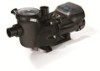
... basket design ensures easy debris removal and extends time between cleanings Motor drive includes built-in terms of Pump Operation per hour Page 7 of the Hayward EcoStar Variable Speed Pump. Introduction This manual contains information for high temperatures and voltage fluctuations. Drive is measured in protection for the proper installation and operation of 36 USE ONLY...
... basket design ensures easy debris removal and extends time between cleanings Motor drive includes built-in terms of Pump Operation per hour Page 7 of the Hayward EcoStar Variable Speed Pump. Introduction This manual contains information for high temperatures and voltage fluctuations. Drive is measured in protection for the proper installation and operation of 36 USE ONLY...
Owners Manual
Page 12
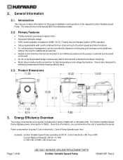
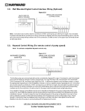
...screws in the wall mount kit using the two screws. (Figure 4.13-3) 8. Disconnect the short cable that extends out from the motor drive. (Figure 4.13-1) 4. Connect the interface cable as shown in the Wall Mounted Digital Control Interface Wiring diagram shown in length. (Figure...screws securing the interface to the motor drive and interface PCB. Mount the wall mount plate, SP3200DR10, in the desired orientation. Install the blank cover, SP3200DR9, on the backside of 36 USE ONLY HAYWARD GENUINE REPLACEMENT PARTS EcoStar Variable Speed Pump IS3401VSP Rev-2 Interface Wall Mounting The ...
...screws in the wall mount kit using the two screws. (Figure 4.13-3) 8. Disconnect the short cable that extends out from the motor drive. (Figure 4.13-1) 4. Connect the interface cable as shown in the Wall Mounted Digital Control Interface Wiring diagram shown in length. (Figure...screws securing the interface to the motor drive and interface PCB. Mount the wall mount plate, SP3200DR10, in the desired orientation. Install the blank cover, SP3200DR9, on the backside of 36 USE ONLY HAYWARD GENUINE REPLACEMENT PARTS EcoStar Variable Speed Pump IS3401VSP Rev-2 Interface Wall Mounting The ...
Owners Manual
Page 14
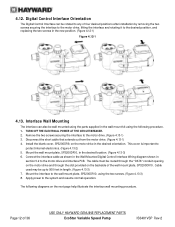
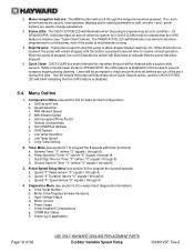
... must be routed through the conduit opening labeled "POWER". Tighten the supplied screw on the motor drive. 3. Wiring Diagrams 5.1. 4.14. If the pump will use the remote stop feature of 36 USE ONLY HAYWARD GENUINE REPLACEMENT PARTS EcoStar Variable Speed Pump IS3401VSP Rev-2 See section 6.6.11 for diagram. 4. Connect 230VAC line power supply wiring to "Configuration...
... must be routed through the conduit opening labeled "POWER". Tighten the supplied screw on the motor drive. 3. Wiring Diagrams 5.1. 4.14. If the pump will use the remote stop feature of 36 USE ONLY HAYWARD GENUINE REPLACEMENT PARTS EcoStar Variable Speed Pump IS3401VSP Rev-2 See section 6.6.11 for diagram. 4. Connect 230VAC line power supply wiring to "Configuration...
Owners Manual
Page 15
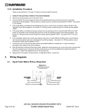
... installation manual or visit our website at www.haywardpool.com. Hayward Control Wiring (For remote control of 36 USE ONLY HAYWARD GENUINE REPLACEMENT PARTS EcoStar Variable Speed Pump IS3401VSP Rev-2 Once installed, Remote Control Mode must be rated for wiring connection to display and motor drive board taking care to note the wire colors and corresponding...
... installation manual or visit our website at www.haywardpool.com. Hayward Control Wiring (For remote control of 36 USE ONLY HAYWARD GENUINE REPLACEMENT PARTS EcoStar Variable Speed Pump IS3401VSP Rev-2 Once installed, Remote Control Mode must be rated for wiring connection to display and motor drive board taking care to note the wire colors and corresponding...
Owners Manual
Page 19
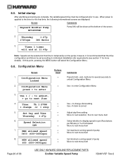
... all bathers are out of 36 USE ONLY HAYWARD GENUINE REPLACEMENT PARTS EcoStar Variable Speed Pump IS3401VSP Rev-2 Set Day and Time b. Low Temp Operation j. Users will illuminate to change parameters. 3. Drive Temp Setting 2. The < and > arrow buttons are used to stop the pump to program the 4 preset speeds) a. Timer Menu (see section 6.8 to allow strainer basket...
... all bathers are out of 36 USE ONLY HAYWARD GENUINE REPLACEMENT PARTS EcoStar Variable Speed Pump IS3401VSP Rev-2 Set Day and Time b. Low Temp Operation j. Users will illuminate to change parameters. 3. Drive Temp Setting 2. The < and > arrow buttons are used to stop the pump to program the 4 preset speeds) a. Timer Menu (see section 6.8 to allow strainer basket...
Owners Manual
Page 20
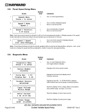
... of the screen. 2. 6.5. Hayward EcoStar Pump SP3400VSP Pump SKU will be shown at this point, pressing the MENU button will end at 11:45p Note: Speeds can be selected at the bottom of 36 USE ONLY HAYWARD GENUINE REPLACEMENT PARTS EcoStar Variable Speed Pump IS3401VSP Rev-2 Thursday 1:27p 1725rpm...first time, the following informational screens are complete, the variable speed drive must be set according to next menu item +- Speed Selection rpm 7. At this time to temporarily run the pump, however, it is applied to the drive for more details). Set Day and Time Thursday 1:27p...
... of the screen. 2. 6.5. Hayward EcoStar Pump SP3400VSP Pump SKU will be shown at this point, pressing the MENU button will end at 11:45p Note: Speeds can be selected at the bottom of 36 USE ONLY HAYWARD GENUINE REPLACEMENT PARTS EcoStar Variable Speed Pump IS3401VSP Rev-2 Thursday 1:27p 1725rpm...first time, the following informational screens are complete, the variable speed drive must be set according to next menu item +- Speed Selection rpm 7. At this time to temporarily run the pump, however, it is applied to the drive for more details). Set Day and Time Thursday 1:27p...
Owners Manual
Page 21
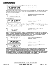
... set in section 5.4) 11. Low Temp Operation Disabled +- The internal drive temperature does not correlate to next menu item 14. Page 21 of 36 USE ONLY HAYWARD GENUINE REPLACEMENT PARTS EcoStar Variable Speed Pump IS3401VSP Rev-2 Set SVRS Restart to Automatic or Manual Move to next menu... item Note: For SP3400VSPVR, the SVRS feature may manually restart the pump prior to the automatic restart by a third...
... set in section 5.4) 11. Low Temp Operation Disabled +- The internal drive temperature does not correlate to next menu item 14. Page 21 of 36 USE ONLY HAYWARD GENUINE REPLACEMENT PARTS EcoStar Variable Speed Pump IS3401VSP Rev-2 Set SVRS Restart to Automatic or Manual Move to next menu... item Note: For SP3400VSPVR, the SVRS feature may manually restart the pump prior to the automatic restart by a third...
Owners Manual
Page 23
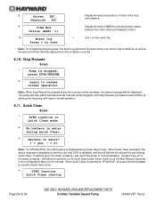
... line voltage status connected to save the new speed setting. 6.9. Power Usage 225W (0-2650W) Real-time display of 36 USE ONLY HAYWARD GENUINE REPLACEMENT PARTS EcoStar Variable Speed Pump IS3401VSP Rev-2 Diagnostic Menu Press > to enter Buttons Used Comments Use > to enter Speeds Menu 2. Serial Number 03100002 Displays motor drive serial number. 3. Input Voltage Within Range Real...
... line voltage status connected to save the new speed setting. 6.9. Power Usage 225W (0-2650W) Real-time display of 36 USE ONLY HAYWARD GENUINE REPLACEMENT PARTS EcoStar Variable Speed Pump IS3401VSP Rev-2 Diagnostic Menu Press > to enter Buttons Used Comments Use > to enter Speeds Menu 2. Serial Number 03100002 Displays motor drive serial number. 3. Input Voltage Within Range Real...
Owners Manual
Page 24
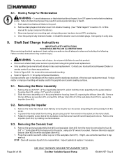
...: 38C Heatsink: 32C Display showing temperature of 36 USE ONLY HAYWARD GENUINE REPLACEMENT PARTS EcoStar Variable Speed Pump IS3401VSP Rev-2 Pump is selected for 60 minutes. SVRS inactive in the water, pressing + will return the pump to alert the user that SVRS is pressed, the above message...Online (Addr: 1) Display showing COMM Bus communication status between the motor drive and Hayward control. 10. Event log Press + to run in Quick Clean mode, where it will run at which point the pump will remain stopped until Stop/Resume is disabled during Quick Clean. 3. Stop...
...: 38C Heatsink: 32C Display showing temperature of 36 USE ONLY HAYWARD GENUINE REPLACEMENT PARTS EcoStar Variable Speed Pump IS3401VSP Rev-2 Pump is selected for 60 minutes. SVRS inactive in the water, pressing + will return the pump to alert the user that SVRS is pressed, the above message...Online (Addr: 1) Display showing COMM Bus communication status between the motor drive and Hayward control. 10. Event log Press + to run in Quick Clean mode, where it will run at which point the pump will remain stopped until Stop/Resume is disabled during Quick Clean. 3. Stop...
Owners Manual
Page 26
...should attempt rotary seal replacement. Contact your local authorized Hayward Dealer or service center if you have any questions. Refer to Figure 9.6-1 for motor drive removal and mounting. Refer to Figure 10.1-1 for pump component locations.) 3. Removing the Impeller 3. To prevent... may result in handling both the rotating and the stationary sections of 36 USE ONLY HAYWARD GENUINE REPLACEMENT PARTS EcoStar Variable Speed Pump IS3401VSP Rev-2 Failure to pump before draining pump. Removing the Motor Assembly 1. Page 26 of the two-part replacement seal.
...should attempt rotary seal replacement. Contact your local authorized Hayward Dealer or service center if you have any questions. Refer to Figure 9.6-1 for motor drive removal and mounting. Refer to Figure 10.1-1 for pump component locations.) 3. Removing the Impeller 3. To prevent... may result in handling both the rotating and the stationary sections of 36 USE ONLY HAYWARD GENUINE REPLACEMENT PARTS EcoStar Variable Speed Pump IS3401VSP Rev-2 Failure to pump before draining pump. Removing the Motor Assembly 1. Page 26 of the two-part replacement seal.
Owners Manual
Page 28
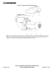
The drive mounting screws must be tightened to 30 inch-pounds. Take care to ensure that the motor leads are not pinched between the drive enclosure and the motor during assembly. Page 28 of 36 USE ONLY HAYWARD GENUINE REPLACEMENT PARTS EcoStar Variable Speed Pump IS3401VSP Rev-2 Figure 9.6-1: Removing the Variable Speed Drive Note: Motor leads must be disconnected prior to removing drive, and reconnected when new drive is mounted.
The drive mounting screws must be tightened to 30 inch-pounds. Take care to ensure that the motor leads are not pinched between the drive enclosure and the motor during assembly. Page 28 of 36 USE ONLY HAYWARD GENUINE REPLACEMENT PARTS EcoStar Variable Speed Pump IS3401VSP Rev-2 Figure 9.6-1: Removing the Variable Speed Drive Note: Motor leads must be disconnected prior to removing drive, and reconnected when new drive is mounted.
Owners Manual
Page 30
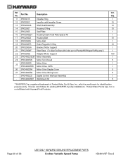
... Motor Assembly 1 24 SPX3400FAN Motor Fan Shroud 5 SPX3400DR Motor Drive 1 25 SPX3400DRVR Motor Drive, SVRS 1 26 SPX3400DR4 Motor Drive Display Cover 5 27 SPX3400DR2 Motor Drive Wiring Cover 5 - Description No. SPX3400LCD Digital Control Interface Assembly 1 - Ref. Ctn. SPX3400DRKIT Wall Mount Kit 5 * WHISPERFLO is a registered trademark of 36 USE ONLY HAYWARD GENUINE REPLACEMENT PARTS EcoStar Variable Speed Pump IS3401VSP Rev-2
... Motor Assembly 1 24 SPX3400FAN Motor Fan Shroud 5 SPX3400DR Motor Drive 1 25 SPX3400DRVR Motor Drive, SVRS 1 26 SPX3400DR4 Motor Drive Display Cover 5 27 SPX3400DR2 Motor Drive Wiring Cover 5 - Description No. SPX3400LCD Digital Control Interface Assembly 1 - Ref. Ctn. SPX3400DRKIT Wall Mount Kit 5 * WHISPERFLO is a registered trademark of 36 USE ONLY HAYWARD GENUINE REPLACEMENT PARTS EcoStar Variable Speed Pump IS3401VSP Rev-2
Owners Manual
Page 33
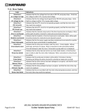
... line voltage is not operating properly, and that the internal components of 36 USE ONLY HAYWARD GENUINE REPLACEMENT PARTS EcoStar Variable Speed Pump IS3401VSP Rev-2 Indicates that the line power supply was not able to be verified. Indicates that the drive memory has been damaged or corrupted, and that the input current limiter is overheated...
... line voltage is not operating properly, and that the internal components of 36 USE ONLY HAYWARD GENUINE REPLACEMENT PARTS EcoStar Variable Speed Pump IS3401VSP Rev-2 Indicates that the line power supply was not able to be verified. Indicates that the drive memory has been damaged or corrupted, and that the input current limiter is overheated...
Technical Guide
Page 1
Variable Speed Pump and Drive Technical Guide © 2011 Hayward Pool Products Version 2 Drive FW 1.02 Interface FW 2.55 residential Interface FW 1.00 commercial
Variable Speed Pump and Drive Technical Guide © 2011 Hayward Pool Products Version 2 Drive FW 1.02 Interface FW 2.55 residential Interface FW 1.00 commercial

Technical Guide
Page 3
... reduce the risk of electric shock, see installation instructions and consult a professional electrician on drive or motor, turn off power supply to the drive. Failure to bond drive to follow all applicable local codes, regulations, and the National Electric Code (NEC). Also, contact a licensed electrician for bonding requirements. Before working on how...
... reduce the risk of electric shock, see installation instructions and consult a professional electrician on drive or motor, turn off power supply to the drive. Failure to bond drive to follow all applicable local codes, regulations, and the National Electric Code (NEC). Also, contact a licensed electrician for bonding requirements. Before working on how...
Technical Guide
Page 9
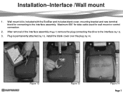
After removal of the interface assembly (Page 7) remove the plug connecting the drive to the interface assembly. Plug is included with the EcoStar and includes blank cover, mounting bracket and new terminal block for wall mount or control connection. 2. Figure 12 Figure 13 Figure 14 Page 7 Installation-Interface /Wall mount 1. Wall mount kit is permanently attached (fig 13), install the blank cover over the plug (fig 14). Maximum 500‟ for data cable used for connecting to the interface (fig 12). 3.
After removal of the interface assembly (Page 7) remove the plug connecting the drive to the interface assembly. Plug is included with the EcoStar and includes blank cover, mounting bracket and new terminal block for wall mount or control connection. 2. Figure 12 Figure 13 Figure 14 Page 7 Installation-Interface /Wall mount 1. Wall mount kit is permanently attached (fig 13), install the blank cover over the plug (fig 14). Maximum 500‟ for data cable used for connecting to the interface (fig 12). 3.

Technical Guide
Page 25
This speed can be adjusted between 600 rpm (17%) and 3450 rpm (100%) by pressing the & buttons. This Temperature can be asked to enable or disable the Low Temp Operation (Default is 1000 rpm (29%). by pressing the & buttons. Setting will turn on the EcoStar, if stopped, to protect the drive . ... both "C" and "F". If the Low Temp Operation is enabled you will be adjusted between 35.6 and 50º F. Press the button to set the Drive Temp Setting (fig 48). In this point you will be asked to continue. 17. The default is Disabled) by pressing the & buttons.(fig 46). ...
This speed can be adjusted between 600 rpm (17%) and 3450 rpm (100%) by pressing the & buttons. This Temperature can be asked to enable or disable the Low Temp Operation (Default is 1000 rpm (29%). by pressing the & buttons. Setting will turn on the EcoStar, if stopped, to protect the drive . ... both "C" and "F". If the Low Temp Operation is enabled you will be adjusted between 35.6 and 50º F. Press the button to set the Drive Temp Setting (fig 48). In this point you will be asked to continue. 17. The default is Disabled) by pressing the & buttons.(fig 46). ...
Technical Guide
Page 32
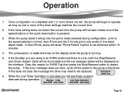
...the drive may need to restart the pump. Clear the reason for SVRS Trip then press the Stop/Resume button to be illuminated and the trip message below will show "Prime Failed" if prime is pressed. 3. If the error message does not clear, cycle off the power to the speed ... the stand alone mode. If the EcoStar you will see these screens Drive Error SVRS Trip alternate during configuration, prior to the pump a few times. Operation 1. If the timer setting does not match the current time the pump will go into the prime mode selected during operation Monday 1:30p 2500...
...the drive may need to restart the pump. Clear the reason for SVRS Trip then press the Stop/Resume button to be illuminated and the trip message below will show "Prime Failed" if prime is pressed. 3. If the error message does not clear, cycle off the power to the speed ... the stand alone mode. If the EcoStar you will see these screens Drive Error SVRS Trip alternate during configuration, prior to the pump a few times. Operation 1. If the timer setting does not match the current time the pump will go into the prime mode selected during operation Monday 1:30p 2500...
Technical Guide
Page 35
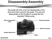
Wiring Compartment Cover Interface Assembly Variable Speed Drive Figure 63 Motor/Fan Shroud Motor Page 33 Disassembly/Assembly This guide will only cover the disassembly of the EcoStar is exactly like the standard TriStar pump. The wet end disassembly of the drive and motor area for this guide.
Wiring Compartment Cover Interface Assembly Variable Speed Drive Figure 63 Motor/Fan Shroud Motor Page 33 Disassembly/Assembly This guide will only cover the disassembly of the EcoStar is exactly like the standard TriStar pump. The wet end disassembly of the drive and motor area for this guide.

Technical Guide
Page 37
Figure 66 Figure 67 Figure 68 Page 35 Remove the plug as shown (fig 66). 4. Remove the interface assembly from the Motor drive (fig 67). 5. Disassembly/Assembly 3. Remove the two screw as shown (fig 68) and place the interface assembly aside.
Figure 66 Figure 67 Figure 68 Page 35 Remove the plug as shown (fig 66). 4. Remove the interface assembly from the Motor drive (fig 67). 5. Disassembly/Assembly 3. Remove the two screw as shown (fig 68) and place the interface assembly aside.


