Owners Manual
Page 3
Replacing the Impeller and Diffuser 27 9.6. Replacing the Motor Assembly 27 10. Replacement Parts ...29 10.1. Removing the Ceramic Seat 26 9.4. Troubleshooting...31 11.1. Product Registration...35 Page 3 of 36 USE ONLY HAYWARD GENUINE REPLACEMENT PARTS EcoStar Variable Speed Pump IS3401VSP Rev-2 Seal Installation 27 9.5. Parts Diagram 29 10.2. Error Codes 33 12. Removing the Motor Assembly 26 9.2. General Problems 31 11.2. Warranty...34 13. 9.1. Parts Listing 29 11. Removing the Impeller 26 9.3.
Replacing the Impeller and Diffuser 27 9.6. Replacing the Motor Assembly 27 10. Replacement Parts ...29 10.1. Removing the Ceramic Seat 26 9.4. Troubleshooting...31 11.1. Product Registration...35 Page 3 of 36 USE ONLY HAYWARD GENUINE REPLACEMENT PARTS EcoStar Variable Speed Pump IS3401VSP Rev-2 Seal Installation 27 9.5. Parts Diagram 29 10.2. Error Codes 33 12. Removing the Motor Assembly 26 9.2. General Problems 31 11.2. Warranty...34 13. 9.1. Parts Listing 29 11. Removing the Impeller 26 9.3.

Owners Manual
Page 18
... Speeds: Speed 1: 1000 rpm Speed 2: 1750 rpm Speed 3: 2500 rpm Speed 4: 3250 rpm Page 18 of suction pipe. Before removing strainer cover: 1. If pump does NOT prime within 15 minutes, stop motor and determine cause. See Troubleshooting ... suction lift and horizontal length of 36 USE ONLY HAYWARD GENUINE REPLACEMENT PARTS EcoStar Variable Speed Pump IS3401VSP Rev-2 User Interface Summary Figure 6.3-1 1. When a speed is running. a. Preset Speeds: Buttons labeled SPEED 1 thru SPEED 4 can be used to pool/spa system directly ...
... Speeds: Speed 1: 1000 rpm Speed 2: 1750 rpm Speed 3: 2500 rpm Speed 4: 3250 rpm Page 18 of suction pipe. Before removing strainer cover: 1. If pump does NOT prime within 15 minutes, stop motor and determine cause. See Troubleshooting ... suction lift and horizontal length of 36 USE ONLY HAYWARD GENUINE REPLACEMENT PARTS EcoStar Variable Speed Pump IS3401VSP Rev-2 User Interface Summary Figure 6.3-1 1. When a speed is running. a. Preset Speeds: Buttons labeled SPEED 1 thru SPEED 4 can be used to pool/spa system directly ...
Owners Manual
Page 24
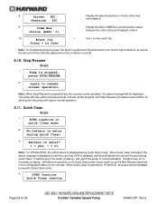
...the pool during Quick Clean mode. If bathers are in water during normal operation, the above message is displayed to view event log Note: For troubleshooting purposes, the Event Log will be displayed. 8. No bathers in the water, pressing + will immediately proceed to normal operation. Note: When ...Page 24 of motor drive chip and heatsink. 9. again to view +- Driver: 38C Heatsink: 32C Display showing temperature of 36 USE ONLY HAYWARD GENUINE REPLACEMENT PARTS EcoStar Variable Speed Pump IS3401VSP Rev-2 SVRS inactive in the Configuration Menu for SP3400VSP, the...
...the pool during Quick Clean mode. If bathers are in water during normal operation, the above message is displayed to view event log Note: For troubleshooting purposes, the Event Log will be displayed. 8. No bathers in the water, pressing + will immediately proceed to normal operation. Note: When ...Page 24 of motor drive chip and heatsink. 9. again to view +- Driver: 38C Heatsink: 32C Display showing temperature of 36 USE ONLY HAYWARD GENUINE REPLACEMENT PARTS EcoStar Variable Speed Pump IS3401VSP Rev-2 SVRS inactive in the Configuration Menu for SP3400VSP, the...

Owners Manual
Page 31
...voltage (230VAC). 3. Strainer basket or skimmer basket loaded with water. You should have 5" - 6" of 36 USE ONLY HAYWARD GENUINE REPLACEMENT PARTS EcoStar Variable Speed Pump IS3401VSP Rev-2 You may be able to verify the electrical connections. Motor Hums, But Does NOT Start: 1.... packing glands on the pump data plate label. 2. Tighten the cover. 5. If the pump develops a vacuum, check for and correct any improper or loose wiring connections; b. ii. Check voltage to create a tighter seal. 2. Air leak in position. Troubleshooting 11.1. Have a qualified...
...voltage (230VAC). 3. Strainer basket or skimmer basket loaded with water. You should have 5" - 6" of 36 USE ONLY HAYWARD GENUINE REPLACEMENT PARTS EcoStar Variable Speed Pump IS3401VSP Rev-2 You may be able to verify the electrical connections. Motor Hums, But Does NOT Start: 1.... packing glands on the pump data plate label. 2. Tighten the cover. 5. If the pump develops a vacuum, check for and correct any improper or loose wiring connections; b. ii. Check voltage to create a tighter seal. 2. Air leak in position. Troubleshooting 11.1. Have a qualified...

Technical Guide
Page 2
Table of Contents Safety Precautions Installation Programming Operation Programming Scenarios Disassembly/Assembly Password/Commercial Diagnostics/Troubleshooting Page 1 Page 2-14 Page 15-29 Page 30-31 Page 32 Page 33-38 Page 39-40 Page 41-48
Table of Contents Safety Precautions Installation Programming Operation Programming Scenarios Disassembly/Assembly Password/Commercial Diagnostics/Troubleshooting Page 1 Page 2-14 Page 15-29 Page 30-31 Page 32 Page 33-38 Page 39-40 Page 41-48
Technical Guide
Page 43
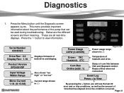
... + button you will see the last 20 error and or trip conditions, as well as the amount of time that can be used during troubleshooting. Reads offline when not connected Event Log Press + to view information. Below are all real-time displays. Also shows "too high" or ...Online (addr: 1) Temperature of both drive and display. Page 41 This menu provides important information about the performance of com link between VSC and Hayward control. Serial Number 03045433 Drive Rev: 2.2 Display Rev: 1.16 Product Version SP3400VSP Input Voltage Within Range Motor Current 1.1A (0-13.0A) ...
... + button you will see the last 20 error and or trip conditions, as well as the amount of time that can be used during troubleshooting. Reads offline when not connected Event Log Press + to view information. Below are all real-time displays. Also shows "too high" or ...Online (addr: 1) Temperature of both drive and display. Page 41 This menu provides important information about the performance of com link between VSC and Hayward control. Serial Number 03045433 Drive Rev: 2.2 Display Rev: 1.16 Product Version SP3400VSP Input Voltage Within Range Motor Current 1.1A (0-13.0A) ...

Technical Guide
Page 44
All other pump problems including seals, gaskets, impellers, etc along with the VSC and Motor. Follow disassembly/assembly procedures (pages 32-37). Clear all debris from lead to ... is within range, replace drive. Page 42 Check impeller, diffuser and shaft seals for blockage. If there are no continuity. Ohms readings should be checked. Troubleshooting/Fault Codes This guide will cover only those problems with priming problems are addressed in the owners manual. Drive Overload Indicates that the motor is...
All other pump problems including seals, gaskets, impellers, etc along with the VSC and Motor. Follow disassembly/assembly procedures (pages 32-37). Clear all debris from lead to ... is within range, replace drive. Page 42 Check impeller, diffuser and shaft seals for blockage. If there are no continuity. Ohms readings should be checked. Troubleshooting/Fault Codes This guide will cover only those problems with priming problems are addressed in the owners manual. Drive Overload Indicates that the motor is...

Technical Guide
Page 45
...If less than 264 VAC, correct incoming supply voltage. Page 43 Check incoming supply voltage, if greater than 264 VAC, refer to Hayward Service Bulletin "Pump Error: Ac Volts too High" and follow instructions for blockage. Follow disassembly/assembly procedures (pages 32-37). PFC Circuit Low Drive ...If line voltage is within +/- 10% of 230 VAC. Clear all debris from the heatsink (page 36) on the bottom of the drive. Troubleshooting/Fault Codes Code/Fault Drive Error! Check incoming line voltage (page 4) and verify that the heatsink on the bottom of the drive (page 36...
...If less than 264 VAC, correct incoming supply voltage. Page 43 Check incoming supply voltage, if greater than 264 VAC, refer to Hayward Service Bulletin "Pump Error: Ac Volts too High" and follow instructions for blockage. Follow disassembly/assembly procedures (pages 32-37). PFC Circuit Low Drive ...If line voltage is within +/- 10% of 230 VAC. Clear all debris from the heatsink (page 36) on the bottom of the drive. Troubleshooting/Fault Codes Code/Fault Drive Error! Check incoming line voltage (page 4) and verify that the heatsink on the bottom of the drive (page 36...

Technical Guide
Page 46
Troubleshooting/Fault Codes Code/Fault Drive Error Drive failed to insure a good connection. Indications Indicates that the drive was not able to start three times before stall error is being controlled via data link to a Hayward/Goldline Controller, disconnect the com ground wire between 0.5 and 1.0 ohms... the motor. Ohms reading should be sure motor shaft turns freely. If pump is displayed. If no continuity. Check values in Diagnosis menu and if they are connected correctly (page 10). Pump will attempt to insure other data wires are within range, replace drive....
Troubleshooting/Fault Codes Code/Fault Drive Error Drive failed to insure a good connection. Indications Indicates that the drive was not able to start three times before stall error is being controlled via data link to a Hayward/Goldline Controller, disconnect the com ground wire between 0.5 and 1.0 ohms... the motor. Ohms reading should be sure motor shaft turns freely. If pump is displayed. If no continuity. Check values in Diagnosis menu and if they are connected correctly (page 10). Pump will attempt to insure other data wires are within range, replace drive....
Technical Guide
Page 47
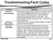
... they are within 15 minutes of these readings are clean.. This code is only enabled in Standalone/Auto Prime mode. Troubleshooting/Fault Codes Code/Fault Drive Error Pump has Stalled Drive Error Memory Failure Drive Error Prime Failed Indications Check impeller and motor shaft for potential air leaks or ... and corrected. Indicates that the drive memory has been damaged or corrupted and drive needs to ground. If the above does not allow the pump to prime, switch from the drive and check each motor lead to be checked for freedom of movement. Check to 3 minute prime (Page...
... they are within 15 minutes of these readings are clean.. This code is only enabled in Standalone/Auto Prime mode. Troubleshooting/Fault Codes Code/Fault Drive Error Pump has Stalled Drive Error Memory Failure Drive Error Prime Failed Indications Check impeller and motor shaft for potential air leaks or ... and corrected. Indicates that the drive memory has been damaged or corrupted and drive needs to ground. If the above does not allow the pump to prime, switch from the drive and check each motor lead to be checked for freedom of movement. Check to 3 minute prime (Page...

Technical Guide
Page 48
... EcoStar is tripping. The breaker is connected to a GL/Hayward control. If still tripping breaker, replace drive. If the values are at "0" replace the interface. It travels on , the pump will ramp up and down in speed. ground and AC ground wire and interferes with the commands...from the control. This is caused by frequency noise emitted from the display and re-connect. ground between the interface and drive. Troubleshooting/Fault Codes Code/Fault Indications Warning NO Comm Inspect the data wire between the control and EcoStar. Install RS485 isolator, or new interface...
... EcoStar is tripping. The breaker is connected to a GL/Hayward control. If still tripping breaker, replace drive. If the values are at "0" replace the interface. It travels on , the pump will ramp up and down in speed. ground and AC ground wire and interferes with the commands...from the control. This is caused by frequency noise emitted from the display and re-connect. ground between the interface and drive. Troubleshooting/Fault Codes Code/Fault Indications Warning NO Comm Inspect the data wire between the control and EcoStar. Install RS485 isolator, or new interface...

Technical Guide
Page 49
... set at the minimum (600rpm/17%) and the maximum (3450rpm/100%) so as to not interfere with a GL/Hayward control. wires between the pump interface and the control Check to make sure the Min and Max setting on in the control (page 5). The %/...rpm reading does not match between GL/Hayward control and EcoStar. bus connection and NOT the input connections for Standalone/Hayward. . The EcoStar should be wired to a dedicated 15 amp double pole breaker. Troubleshooting/Fault Codes Code/Fault Indications EcoStar is set to variable speed . Check comm.
... set at the minimum (600rpm/17%) and the maximum (3450rpm/100%) so as to not interfere with a GL/Hayward control. wires between the pump interface and the control Check to make sure the Min and Max setting on in the control (page 5). The %/...rpm reading does not match between GL/Hayward control and EcoStar. bus connection and NOT the input connections for Standalone/Hayward. . The EcoStar should be wired to a dedicated 15 amp double pole breaker. Troubleshooting/Fault Codes Code/Fault Indications EcoStar is set to variable speed . Check comm.

Technical Guide
Page 50
...When a command is active. Remove wires and connect to operate via the GL/Hayward control. It will not and should not be expected to protect any plumbing or other devices to come on the pump interface do not work properly. Try changing channel on the drive (page 10). ... the GL/Hayward control. Page 48 If problem persists, purchase (2) model XPF 20A 3-wire noise filters through X-10 website. When the control is operating the EcoStar, the Speed buttons and the Quick Clean button is correct. The Speed buttons and Quick Clean buttons on and off. Troubleshooting/Fault Codes ...
...When a command is active. Remove wires and connect to operate via the GL/Hayward control. It will not and should not be expected to protect any plumbing or other devices to come on the pump interface do not work properly. Try changing channel on the drive (page 10). ... the GL/Hayward control. Page 48 If problem persists, purchase (2) model XPF 20A 3-wire noise filters through X-10 website. When the control is operating the EcoStar, the Speed buttons and the Quick Clean button is correct. The Speed buttons and Quick Clean buttons on and off. Troubleshooting/Fault Codes ...


