Salt & Swim Owner's Manual
Page 3
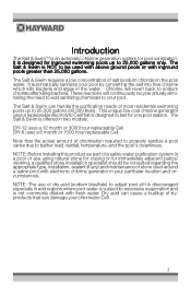
... (if any) and maintenance of salt (sodium chloride) in two models: DIY-12 uses a 12 month or 3000 hour replaceable Cell DIY-6 uses a 6 month or 1500 hour replaceable Cell Note that can damage your pool. The Salt & Swim is designed for pool sanitization. Chlorine...chlorine generator uses a replaceable electrolytic Cell that is not commonly diluted with fresh water. The Salt & Swim is an automatic chlorine generation system for inground swimming pools up to bather load, rainfall, temperature, and the pool's cleanliness. The Salt & Swim requires a low concentration of stone ...
... (if any) and maintenance of salt (sodium chloride) in two models: DIY-12 uses a 12 month or 3000 hour replaceable Cell DIY-6 uses a 6 month or 1500 hour replaceable Cell Note that can damage your pool. The Salt & Swim is designed for pool sanitization. Chlorine...chlorine generator uses a replaceable electrolytic Cell that is not commonly diluted with fresh water. The Salt & Swim is an automatic chlorine generation system for inground swimming pools up to bather load, rainfall, temperature, and the pool's cleanliness. The Salt & Swim requires a low concentration of stone ...
Salt & Swim Owner's Manual
Page 4
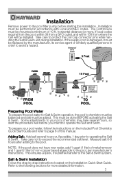
... persons in accordance with Local and NEC codes. Measure salt 6-8 hours after adding to operating the Salt & Swim . Refer to the following sections for Salt & Swim operation, the pool's chemistry must be balanced and salt must be installed. Waterproof GFCI Outlet 3 Feet 15 Feet...within 15ft from where the Cell will be added. This ensures a quick, troublefree transfer to protect the Cell Cap connector pins while handling the Salt & Swim unit during installation. Take care to the Salt & Swim system. This must be done BEFORE activating the Salt & Swim. Take care not to...
... persons in accordance with Local and NEC codes. Measure salt 6-8 hours after adding to operating the Salt & Swim . Refer to the following sections for Salt & Swim operation, the pool's chemistry must be balanced and salt must be installed. Waterproof GFCI Outlet 3 Feet 15 Feet...within 15ft from where the Cell will be added. This ensures a quick, troublefree transfer to protect the Cell Cap connector pins while handling the Salt & Swim unit during installation. Take care to the Salt & Swim system. This must be done BEFORE activating the Salt & Swim. Take care not to...
Salt & Swim Owner's Manual
Page 5
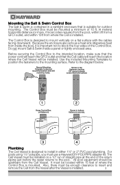
...15 feet of a GFCI outlet, making sure that the cord will reach. Mounting the Salt & Swim Control Box The Salt & Swim is contained in a raintight enclosure that the Cell cable will reach the location where the Cell Vessel will be installed. The Control Box must be upstream from the Vessel after the Vessel...Use the included hardware or your own hardware (suitable fora 20lb load) to mount the Control Box to insert and remove the Cell from the Cell Vessel. Do not mount Salt & Swim inside the box), it is installed. The Cell Vessel must use a Hayward DIY-POLYPIPE adapter kit.
...15 feet of a GFCI outlet, making sure that the cord will reach. Mounting the Salt & Swim Control Box The Salt & Swim is contained in a raintight enclosure that the Cell cable will reach the location where the Cell Vessel will be installed. The Control Box must be upstream from the Vessel after the Vessel...Use the included hardware or your own hardware (suitable fora 20lb load) to mount the Control Box to insert and remove the Cell from the Cell Vessel. Do not mount Salt & Swim inside the box), it is installed. The Cell Vessel must use a Hayward DIY-POLYPIPE adapter kit.

Salt & Swim Owner's Manual
Page 6
... the pump and water drained from the pool plumbing, secure the Cutting Template to the location where the Cell Vessel will not fit. The entire Cutting Template must fit on the pipe otherwise the Cell Vessel will be 12 marks on the pipe as shown below. Be sure to complete Vessel installation... Start Guide to place the Nut, Compression Ring and Collar on t he pipe. Place Nut Assembly on pipe 4 Use a waterproof permanent marker to the desired Cell Vessel inst allation location. When finished, there should be installed. Note that the Cutting Template is the same width as the...
... the pump and water drained from the pool plumbing, secure the Cutting Template to the location where the Cell Vessel will not fit. The entire Cutting Template must fit on the pipe otherwise the Cell Vessel will be 12 marks on the pipe as shown below. Be sure to complete Vessel installation... Start Guide to place the Nut, Compression Ring and Collar on t he pipe. Place Nut Assembly on pipe 4 Use a waterproof permanent marker to the desired Cell Vessel inst allation location. When finished, there should be installed. Note that the Cutting Template is the same width as the...

Salt & Swim Owner's Manual
Page 7
...Nuts to stop, then continue 1/4 turn 7 IMPORTANT: Inspection Marks should not be seen, the pipe has not been inserted far enough into the Cell Vessel. Secure the Vessel to the cut pipe by tightening the Nuts as shown below. O-Ring 5 Verify that the O-Ring is attached before ...inserting the Cell into the Cell Vessel. Position the Vessel in place Insert Cell 6 Vessel and hand tighten Nuts Use the included strap wrench to tighten an additional 1/4 turn more using the included...
...Nuts to stop, then continue 1/4 turn 7 IMPORTANT: Inspection Marks should not be seen, the pipe has not been inserted far enough into the Cell Vessel. Secure the Vessel to the cut pipe by tightening the Nuts as shown below. O-Ring 5 Verify that the O-Ring is attached before ...inserting the Cell into the Cell Vessel. Position the Vessel in place Insert Cell 6 Vessel and hand tighten Nuts Use the included strap wrench to tighten an additional 1/4 turn more using the included...
Salt & Swim Owner's Manual
Page 8
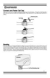
...NEC codes), a bonding lug is provided at the same electrical potential. Cell Cap Retaining Nut Bonding Pool bonding or "equipotential bonding" ensures that all pool components around the pool are at the bottom of the Salt & Swim enclosure. If bonding is required at your pool's existing bonding loop.... Connect and Fasten Cell Cap Slip the Cell Cap through the Retaining Nut as shown below. Run an eight gauge (8 AWG) solid...
...NEC codes), a bonding lug is provided at the same electrical potential. Cell Cap Retaining Nut Bonding Pool bonding or "equipotential bonding" ensures that all pool components around the pool are at the bottom of the Salt & Swim enclosure. If bonding is required at your pool's existing bonding loop.... Connect and Fasten Cell Cap Slip the Cell Cap through the Retaining Nut as shown below. Run an eight gauge (8 AWG) solid...

Salt & Swim Owner's Manual
Page 9
...on for at least 15 seconds. 4. Turn the filter pump OFF. 5. The Salt & Swim should now display a solid INADEQUATE WATER FLOW and a solid STANDING BY LED. Make sure that the Cell's flow switch is complete. Flow Switch Calibration Procedure IMPORTANT: Before going any further,... the Salt & Swim powered for Salt & Swim operation. After the flow switch is initialized, the Salt & Swim will run the pump for the first time, the Salt & Swim will not perform this procedure again until the Cell is installed. You can take up , or when a new Cell is installed, the Salt & Swim will ...
...on for at least 15 seconds. 4. Turn the filter pump OFF. 5. The Salt & Swim should now display a solid INADEQUATE WATER FLOW and a solid STANDING BY LED. Make sure that the Cell's flow switch is complete. Flow Switch Calibration Procedure IMPORTANT: Before going any further,... the Salt & Swim powered for Salt & Swim operation. After the flow switch is initialized, the Salt & Swim will run the pump for the first time, the Salt & Swim will not perform this procedure again until the Cell is installed. You can take up , or when a new Cell is installed, the Salt & Swim will ...
Salt & Swim Owner's Manual
Page 14
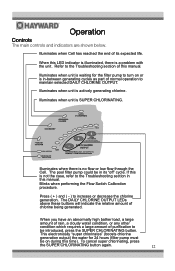
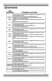
Illuminates when unit is no flow or low flow through the Cell. If this is a problem with the unit. When you have an abnormally high bather load, a large amount of rain, a cloudy water condition, or any other .... The DAILY CHLORINE OUTPUT LEDs above these buttons will indicate the relative amount of purification to the Troubleshooting section of its "off" cycle. Illuminates when Cell has reached the end of this time). When this manual. Refer to be introduced, press the SUPER CHLORINATING button. Illuminates when there is actively generating...
Illuminates when unit is no flow or low flow through the Cell. If this is a problem with the unit. When you have an abnormally high bather load, a large amount of rain, a cloudy water condition, or any other .... The DAILY CHLORINE OUTPUT LEDs above these buttons will indicate the relative amount of purification to the Troubleshooting section of its "off" cycle. Illuminates when Cell has reached the end of this time). When this manual. Refer to be introduced, press the SUPER CHLORINATING button. Illuminates when there is actively generating...

Salt & Swim Owner's Manual
Page 15
...first applied to generate enough chlorine. When the routine is 50º - 60ºF. Because the chlorine demand of operation. The Salt & Swim automatically scales back to find the optimum setting, start the operation with temperature, most people find they have to be closed. the ... factors that is perfectly normal and does not require any input from the Salt & Swim unless pool components are illuminated, the Salt & Swim unit will be set higher than normal bather load or when the Salt & Swim Cell ages. 13 During this time, various LEDs will be plugged into a GFCI...
...first applied to generate enough chlorine. When the routine is 50º - 60ºF. Because the chlorine demand of operation. The Salt & Swim automatically scales back to find the optimum setting, start the operation with temperature, most people find they have to be closed. the ... factors that is perfectly normal and does not require any input from the Salt & Swim unless pool components are illuminated, the Salt & Swim unit will be set higher than normal bather load or when the Salt & Swim Cell ages. 13 During this time, various LEDs will be plugged into a GFCI...

Salt & Swim Owner's Manual
Page 16
...is not submerged. Soak the Cell for any freezing conditions occur. In areas of balance," the Cell may require periodic cleaning. You may need to remove the Cell. Servicing and Cleaning the Salt & Swim Cell Unplug the Salt & Swim from the GFCI outlet and ...remove power from the pump, filter, and supply and return lines before attempting to lower the setting when the pool water temperature decreases significantly or there are long periods of Vessel. Unplug the Cell cord from the Vessel by freezing water just as the popular Hayward Turbo Cell...
...is not submerged. Soak the Cell for any freezing conditions occur. In areas of balance," the Cell may require periodic cleaning. You may need to remove the Cell. Servicing and Cleaning the Salt & Swim Cell Unplug the Salt & Swim from the GFCI outlet and ...remove power from the pump, filter, and supply and return lines before attempting to lower the setting when the pool water temperature decreases significantly or there are long periods of Vessel. Unplug the Cell cord from the Vessel by freezing water just as the popular Hayward Turbo Cell...
Salt & Swim Owner's Manual
Page 17
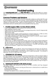
... the pool/spa water is powered. "Yellow Out" or similar treatment recently used. LEDs not on Depending on Cell. - STANDING BY LED blinking The Salt & Swim has shut down the Salt & Swim. 4. Salt level too high - If no obstructions or restrictions in the pool plumbing. - The system will use chlorine at... residual free chlorine. To aid in and that the linecord is plugged in interpreting these indications, Hayward has created an interactive tool located at least one LED illuminated when the Salt & Swim is too high (120ºF) or too low (50ºF). Filter pump time too short...
... the pool/spa water is powered. "Yellow Out" or similar treatment recently used. LEDs not on Depending on Cell. - STANDING BY LED blinking The Salt & Swim has shut down the Salt & Swim. 4. Salt level too high - If no obstructions or restrictions in the pool plumbing. - The system will use chlorine at... residual free chlorine. To aid in and that the linecord is plugged in interpreting these indications, Hayward has created an interactive tool located at least one LED illuminated when the Salt & Swim is too high (120ºF) or too low (50ºF). Filter pump time too short...
Salt & Swim Owner's Manual
Page 18
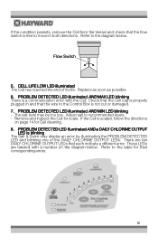
... CHLORINE OUTPUT LED is free to the diagram below . If the condition persists, remove the Cell from the Vessel and check that the flow switch is blinking The Salt & Swim may be too low. CELL LIFE LOW LED illuminated The Cell has reached the end of the DAILY CHLORINE OUTPUT LEDs. Check that the... Cell cap is properly plugged in both directions. PROBLEM DETECTED LED illuminated AND MAX LED ...
... CHLORINE OUTPUT LED is free to the diagram below . If the condition persists, remove the Cell from the Vessel and check that the flow switch is blinking The Salt & Swim may be too low. CELL LIFE LOW LED illuminated The Cell has reached the end of the DAILY CHLORINE OUTPUT LEDs. Check that the... Cell cap is properly plugged in both directions. PROBLEM DETECTED LED illuminated AND MAX LED ...
Salt & Swim Owner's Manual
Page 19
...the temperature does not exceed 104F. 3. Contact Hayward Technical Service. 1. Check that connects the cell to the Salt & Swim by unplugging the linecord for two minutes and then plugging it back in . 2. Recycle power to the Salt & Swim by unplugging the linecord for two minutes Inadequate ... is secure and undamaged. 5. Check that connects the cell to the Salt & Swim by unplugging the linecord for two minutes and then plugging it back in . 2. Contact Hayward Technical Service. Inspect the Cell Vessel and verify the cell plates are fully covered by moving water. 4. Recycle ...
...the temperature does not exceed 104F. 3. Contact Hayward Technical Service. 1. Check that connects the cell to the Salt & Swim by unplugging the linecord for two minutes and then plugging it back in . 2. Recycle power to the Salt & Swim by unplugging the linecord for two minutes Inadequate ... is secure and undamaged. 5. Check that connects the cell to the Salt & Swim by unplugging the linecord for two minutes and then plugging it back in . 2. Contact Hayward Technical Service. Inspect the Cell Vessel and verify the cell plates are fully covered by moving water. 4. Recycle ...

Salt & Swim Owner's Manual
Page 23
...CHLORINATION PRODUCTS, THESE WARRANTIES ALSO ARE VOID IF, DURING THE WARRANTY PERIOD, YOU USE A REPLACEMENT CHLORINATOR CELL OTHER THAN AN UNMODIFIED, NEW HAYWARD CHLORINATOR CELL PURCHASED FROM HAYWARD. Proof of purchase is producing chlorine. Problems resulting from failure to the original owner. SOME STATES DO... EXPENSES, EVEN IF THE SELLER HAD BEEN ADVISED OF THE POSSIBILITY OF SUCH DAMAGES. LIMITED WARRANTY (effective 03/01/12) Hayward warrants its Salt & Swim chlorination products to be free of defects in materials and workmanship, under normal use and service as follows: Control Box - ...
...CHLORINATION PRODUCTS, THESE WARRANTIES ALSO ARE VOID IF, DURING THE WARRANTY PERIOD, YOU USE A REPLACEMENT CHLORINATOR CELL OTHER THAN AN UNMODIFIED, NEW HAYWARD CHLORINATOR CELL PURCHASED FROM HAYWARD. Proof of purchase is producing chlorine. Problems resulting from failure to the original owner. SOME STATES DO... EXPENSES, EVEN IF THE SELLER HAD BEEN ADVISED OF THE POSSIBILITY OF SUCH DAMAGES. LIMITED WARRANTY (effective 03/01/12) Hayward warrants its Salt & Swim chlorination products to be free of defects in materials and workmanship, under normal use and service as follows: Control Box - ...

Salt & Swim Installation Quick Start Guide
Page 1
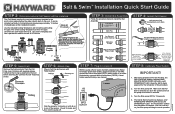
...pool (see Chemistry Quickstart Guide) Installation Preparation Read this entire Quickstart Guide Remove power to filter pump Drain water from the pool. WWW.HAYWARD.COM 855-429-9274 Turn Over Use the included Mounting Template to help locate the mounting holes and fasten the Control Box to the intended...will be installed at least 10 feet away from pool piping Verify that the cord will be mounted within 15ft of the Cell Vessel as shown in the Overview. Salt & SwimTM Installation Quick Start Guide Before you begin Pre-Installation Checklist Pool is less than 25,000 gallons There is at...
...pool (see Chemistry Quickstart Guide) Installation Preparation Read this entire Quickstart Guide Remove power to filter pump Drain water from the pool. WWW.HAYWARD.COM 855-429-9274 Turn Over Use the included Mounting Template to help locate the mounting holes and fasten the Control Box to the intended...will be installed at least 10 feet away from pool piping Verify that the cord will be mounted within 15ft of the Cell Vessel as shown in the Overview. Salt & SwimTM Installation Quick Start Guide Before you begin Pre-Installation Checklist Pool is less than 25,000 gallons There is at...
Salt & Swim Installation Quick Start Guide
Page 2
... fit. Make sure that the O-ring is out of the system. The Salt & Swim should now display a solid INADEQUATE WATER FLOW and a solid STANDING BY LED. Salt & SwimTM Installation Quick Start Guide STEP 2: Determine where Cell Vessel will be installed The Cell Vessel must fit on your filter pump and begin normal operation. 092464 RevB...
... fit. Make sure that the O-ring is out of the system. The Salt & Swim should now display a solid INADEQUATE WATER FLOW and a solid STANDING BY LED. Salt & SwimTM Installation Quick Start Guide STEP 2: Determine where Cell Vessel will be installed The Cell Vessel must fit on your filter pump and begin normal operation. 092464 RevB...


