
Salt & Swim Owner's Manual
Page 1
092463 RevA Salt & SwimTM Chlorine Generator for Inground Swimming Pools up to 25,000 gallons Owner's Manual Contents Introduction 1 Installation 2-8 Operation 12-14 Troubleshooting........15 Warranty 21 DIY-12 DIY-6 Hayward Pool Product 620 Division Street, Elizabeth, NJ 07207 www.hayward.com USE ONLY HAYWARD GENUINE REPLACEMENT PARTS
092463 RevA Salt & SwimTM Chlorine Generator for Inground Swimming Pools up to 25,000 gallons Owner's Manual Contents Introduction 1 Installation 2-8 Operation 12-14 Troubleshooting........15 Warranty 21 DIY-12 DIY-6 Hayward Pool Product 620 Division Street, Elizabeth, NJ 07207 www.hayward.com USE ONLY HAYWARD GENUINE REPLACEMENT PARTS
Salt & Swim Owner's Manual
Page 3
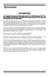
... and is not commonly diluted with inground pools greater than 25,000 gallons. The Salt & Swim is NOT to 25,000 gallons only. The Salt & Swim requires a low concentration of most residential swimming pools up to be consulted regarding the appropriate type, installation, sealant (if any) and maintenance of stone used with above ground pools or...
... and is not commonly diluted with inground pools greater than 25,000 gallons. The Salt & Swim is NOT to 25,000 gallons only. The Salt & Swim requires a low concentration of most residential swimming pools up to be consulted regarding the appropriate type, installation, sealant (if any) and maintenance of stone used with above ground pools or...
Salt & Swim Owner's Manual
Page 4
... pool chemistry may take several hours or, if possible, 1 day prior to the pool, per manufacturer's instructions. Measure salt 6-8 hours after adding to exceed the recommended salt level. Take care not to the pool. Salt & Swim Installation Follow the step by the manufacturer, its service agent or similarly qualified persons in accordance with Local and...
... pool chemistry may take several hours or, if possible, 1 day prior to the pool, per manufacturer's instructions. Measure salt 6-8 hours after adding to exceed the recommended salt level. Take care not to the pool. Salt & Swim Installation Follow the step by the manufacturer, its service agent or similarly qualified persons in accordance with Local and...
Salt & Swim Owner's Manual
Page 5
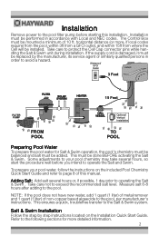
...Hayward DIY-POLYPIPE adapter kit. Use the included Mounting Template to position the fasteners to the diagram below. Refer to the mounting surface. After ma rkin g the moun tin g surface w ith this templateto locateand drillfastenerholes. All pool equipment should be upstream from the Vessel after the Vessel is installed. 3 Do not mount Salt & Swim...making sure that is suitable for outdoor mounting. Mounting the Salt & Swim Control Box The Salt & Swim is contained in a raintight enclosure that the cord will be installed. The Control Box is designed to mount vertically on ...
...Hayward DIY-POLYPIPE adapter kit. Use the included Mounting Template to position the fasteners to the diagram below. Refer to the mounting surface. After ma rkin g the moun tin g surface w ith this templateto locateand drillfastenerholes. All pool equipment should be upstream from the Vessel after the Vessel is installed. 3 Do not mount Salt & Swim...making sure that is suitable for outdoor mounting. Mounting the Salt & Swim Control Box The Salt & Swim is contained in a raintight enclosure that the cord will be installed. The Control Box is designed to mount vertically on ...

Salt & Swim Owner's Manual
Page 9
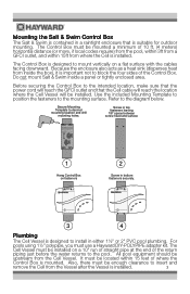
GFCI OUTLET After being powered on for the first time, the Salt & Swim will run the pump for at least 15 seconds. 4. The Flow Switch Calibration procedure is installed. Make sure that full flow is achieved (no air in the system) and run a Flow Switch Calibration procedure to the ...Troubleshooting section of this procedure, refer to ensure that the Cell's flow switch is properly initialized. If the INADEQUATE WATER FLOW LED is installed, the Salt & Swim will run a diagnostic routine which can now turn on how to your pool. At start-up to 30 seconds. After the flow ...
GFCI OUTLET After being powered on for the first time, the Salt & Swim will run the pump for at least 15 seconds. 4. The Flow Switch Calibration procedure is installed. Make sure that full flow is achieved (no air in the system) and run a Flow Switch Calibration procedure to the ...Troubleshooting section of this procedure, refer to ensure that the Cell's flow switch is properly initialized. If the INADEQUATE WATER FLOW LED is installed, the Salt & Swim will run a diagnostic routine which can now turn on how to your pool. At start-up to 30 seconds. After the flow ...

Salt & Swim Owner's Manual
Page 23
... the sole determinant of the date of installation of the product. If written proof of purchase is not transferable and applies only to the original owner. LIMITED WARRANTY (effective 03/01/12) Hayward warrants its Salt & Swim chlorination products to be free of defects in... or 3000 operational hours, whichever comes first Operational hours are determined by reading an embedded logging device inside of the Salt & Swim product. Hayward warrants all accessories and other replacement parts for the above-identified chlorination products for warranty service. FOR THE ABOVE-IDENTIFIED ...
... the sole determinant of the date of installation of the product. If written proof of purchase is not transferable and applies only to the original owner. LIMITED WARRANTY (effective 03/01/12) Hayward warrants its Salt & Swim chlorination products to be free of defects in... or 3000 operational hours, whichever comes first Operational hours are determined by reading an embedded logging device inside of the Salt & Swim product. Hayward warrants all accessories and other replacement parts for the above-identified chlorination products for warranty service. FOR THE ABOVE-IDENTIFIED ...
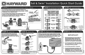
Salt & Swim Installation Quick Start Guide
Page 2
... a blinking INADEQUATE WATER FLOW LED and a solid STANDING BY LED. The entire Cutting Template must be installed vertically or horizontally and requires approximately 10 inches of the system. Keep the Salt & Swim powered for 15 seconds. 4. The Salt & Swim should now display a solid INADEQUATE WATER FLOW and a solid STANDING BY LED. You can be the...
... a blinking INADEQUATE WATER FLOW LED and a solid STANDING BY LED. The entire Cutting Template must be installed vertically or horizontally and requires approximately 10 inches of the system. Keep the Salt & Swim powered for 15 seconds. 4. The Salt & Swim should now display a solid INADEQUATE WATER FLOW and a solid STANDING BY LED. You can be the...


