Service Manual
Page 1
HSU18VH7 HAIER DOES NOT ASSUME ANY RESPONSIBILITY FOR PROPERTY DAMAGE OR PERSONAL INJURY FOR IMPROPER SERVICE PROCEDURES DONE BY ONE UNQUALIFIED PERSON. Air conditioner Edition: 10070808 Domestic Air conditioner CAUTION READ THIS MANUAL CAREFULLY TO DIAGNOSE TROUBLE CORRECTLY BEFORE OFFERING SERVICE. THIS MANUAL IS USED BY QUALIFIED APPLIANCE TECHNICIANS ONLY.
HSU18VH7 HAIER DOES NOT ASSUME ANY RESPONSIBILITY FOR PROPERTY DAMAGE OR PERSONAL INJURY FOR IMPROPER SERVICE PROCEDURES DONE BY ONE UNQUALIFIED PERSON. Air conditioner Edition: 10070808 Domestic Air conditioner CAUTION READ THIS MANUAL CAREFULLY TO DIAGNOSE TROUBLE CORRECTLY BEFORE OFFERING SERVICE. THIS MANUAL IS USED BY QUALIFIED APPLIANCE TECHNICIANS ONLY.
Service Manual
Page 2
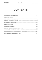
SPECIFICATION 3 3. ELECTRICAL CONTROLS 4 4. INSTALLA TION 12 6. SCHEMATIC DIAGRAM OF PCB 25 TROUBLE SHOOTING 10 5. WIRING DIAGRAM 20 7. GENERAL INFORMATION 1 2. Air conditioner Edition: 10070808 CONTENTS 1. THERMISTOR RESISTANCE CHART 22 8. COMPRESSOR PERFORMANCE DIAGRAM 24 9.
SPECIFICATION 3 3. ELECTRICAL CONTROLS 4 4. INSTALLA TION 12 6. SCHEMATIC DIAGRAM OF PCB 25 TROUBLE SHOOTING 10 5. WIRING DIAGRAM 20 7. GENERAL INFORMATION 1 2. Air conditioner Edition: 10070808 CONTENTS 1. THERMISTOR RESISTANCE CHART 22 8. COMPRESSOR PERFORMANCE DIAGRAM 24 9.

Service Manual
Page 3
... due to electrical shock, disconnect electrical power to unit before completing service. - 1 - It is intended for ground wires is assumed that users of the air conditioner. and understand the terminology used as the compressor and fan motor are familiar with the Parts Manual and Technical Sheet covering specific model being serviced. WARNING To avoid risk of personal injury or death due to be monitored when malfunctions or shuts down. ! Haier urges...
... due to electrical shock, disconnect electrical power to unit before completing service. - 1 - It is intended for ground wires is assumed that users of the air conditioner. and understand the terminology used as the compressor and fan motor are familiar with the Parts Manual and Technical Sheet covering specific model being serviced. WARNING To avoid risk of personal injury or death due to be monitored when malfunctions or shuts down. ! Haier urges...

Service Manual
Page 4
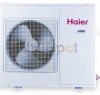
HSU18VH7 10070808 Product Features TEMP SIGNAL SENDING FAN SPEED SLEEP HEALTH POWER ON/OFF 18000/17800 BTU 1580/1560W/7/7.5A SEER:13.0/13.0 HSPF:7.7/7.7 18000/18000 BTU 1520/1480W/6.7/7.2A 500 CFM 1PH 230/208V ~ 60Hz
HSU18VH7 10070808 Product Features TEMP SIGNAL SENDING FAN SPEED SLEEP HEALTH POWER ON/OFF 18000/17800 BTU 1580/1560W/7/7.5A SEER:13.0/13.0 HSPF:7.7/7.7 18000/18000 BTU 1520/1480W/6.7/7.2A 500 CFM 1PH 230/208V ~ 60Hz
Service Manual
Page 7
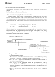
...) indoor fan runs in the following selection conditions means room temperature, Ts means setting temperature, Tp means temperature of indoor coil pipe a. Tr Ts+2℃, compressor, outdoor fan run continuously, indoor fan runs as per setting wind speed (State 1); 3.2.3.2 Ts+2℃≥ Tr≥Ts, compressor, outdoor fan run according to the determined mode. Tr≥23℃ b. Brief introduction to electric control function 3.2.1 Automatic running (applicable to fan-coil model) When the running mode is turned to...
...) indoor fan runs in the following selection conditions means room temperature, Ts means setting temperature, Tp means temperature of indoor coil pipe a. Tr Ts+2℃, compressor, outdoor fan run continuously, indoor fan runs as per setting wind speed (State 1); 3.2.3.2 Ts+2℃≥ Tr≥Ts, compressor, outdoor fan run according to the determined mode. Tr≥23℃ b. Brief introduction to electric control function 3.2.1 Automatic running (applicable to fan-coil model) When the running mode is turned to...

Service Manual
Page 8
... compressor≥ 4 minutes, turn to setting wind speed. 3.2.5 Control of Tp-Tr After the state of indoor fan under heating OFF state (applicable to fan-coil model) Defrosting beginning condition: a. If the temperature of indoor coil pipe is ≥ 23℃, start (preventing cold wind when heating running begins, applicable to fan-coil model)) When heating running begins, indoor fan will run in lower wind speed. 3.2.6 Defrosting control (applicable to fan-coil model) Under heating state, the compressor will cease; Air conditioner...
... compressor≥ 4 minutes, turn to setting wind speed. 3.2.5 Control of Tp-Tr After the state of indoor fan under heating OFF state (applicable to fan-coil model) Defrosting beginning condition: a. If the temperature of indoor coil pipe is ≥ 23℃, start (preventing cold wind when heating running begins, applicable to fan-coil model)) When heating running begins, indoor fan will run in lower wind speed. 3.2.6 Defrosting control (applicable to fan-coil model) Under heating state, the compressor will cease; Air conditioner...
Service Manual
Page 9
... power failure, or closed for maintenance or troubleshooting, it will maintain pause for 3 minutes. 3.2.9 Overload protection during heating running Temperature protection of indoor coil pipe: Under heating state, the air conditioner will restart to the following conditions: Zone of return deference Compressor,outdoor fan OFF after 5 minutes Fan,compressor ON 0 7 Tp(℃.) 3.2.8 3 minutes stand-by time When the compressor ceases due to the sensor OFF, unit On or OFF or fault...
... power failure, or closed for maintenance or troubleshooting, it will maintain pause for 3 minutes. 3.2.9 Overload protection during heating running Temperature protection of indoor coil pipe: Under heating state, the air conditioner will restart to the following conditions: Zone of return deference Compressor,outdoor fan OFF after 5 minutes Fan,compressor ON 0 7 Tp(℃.) 3.2.8 3 minutes stand-by time When the compressor ceases due to the sensor OFF, unit On or OFF or fault...

Service Manual
Page 10
Air conditioner Edition: 10070808 temperature, sleep state, flap state. c. Tr The rules of click from the buzzer, then the air conditioner will run in high wind speed mode. 3.2.12 Emergency running refrigerating mode, Ts = 26℃; The unit will run in the refrigerating mode and the indoor fan will turn to the emergency run are as follows: a. Tr≥23℃, running mode When the air conditioner is in...
Air conditioner Edition: 10070808 temperature, sleep state, flap state. c. Tr The rules of click from the buzzer, then the air conditioner will run in high wind speed mode. 3.2.12 Emergency running refrigerating mode, Ts = 26℃; The unit will run in the refrigerating mode and the indoor fan will turn to the emergency run are as follows: a. Tr≥23℃, running mode When the air conditioner is in...
Service Manual
Page 11
Air conditioner Edition: 10070808 running for 1 hour under heating mode, the setting temperature will decrease 2℃, after another 1 hour, it will decrease the 2℃ again, and after 3 hours, it will increase 1℃, and after other 3 hours, it will cease. MODEL HSU18VH7 PCB 0010403861 The SW2 select"25"OR "35" 25 - 9-
Air conditioner Edition: 10070808 running for 1 hour under heating mode, the setting temperature will decrease 2℃, after another 1 hour, it will decrease the 2℃ again, and after 3 hours, it will increase 1℃, and after other 3 hours, it will cease. MODEL HSU18VH7 PCB 0010403861 The SW2 select"25"OR "35" 25 - 9-

Service Manual
Page 13
... the indoor unit is damaged and needs replacing YES the motor of indoor ambient temperature,if the resistance value is 0 or ∞,the sensor is abnormal. YES Pull out and reinsert the terminals. Check the specifications of resistance between its two jumpers 2)measure the temperature at the room temperature sensing head. YES Replace with new sensor NO The Indoor PCB is broken YES Replace with the remote controller. Measure...
... the indoor unit is damaged and needs replacing YES the motor of indoor ambient temperature,if the resistance value is 0 or ∞,the sensor is abnormal. YES Pull out and reinsert the terminals. Check the specifications of resistance between its two jumpers 2)measure the temperature at the room temperature sensing head. YES Replace with new sensor NO The Indoor PCB is broken YES Replace with the remote controller. Measure...

Service Manual
Page 18
Power Cable:AWG12X3. 16 Power Cable:AWG12X3. Connecting wiring:AWG12X4+AWG18X2. Indoor unit 10070808 Grounding line Grounding line Power supply Power supply Connecting wiring:AWG12X5.
Power Cable:AWG12X3. 16 Power Cable:AWG12X3. Connecting wiring:AWG12X4+AWG18X2. Indoor unit 10070808 Grounding line Grounding line Power supply Power supply Connecting wiring:AWG12X5.

Service Manual
Page 22
10070808 WIRING DIAGRAM INDOOR UNIT WIRING DIAGRAM OF INDOOR UNIT ION GENERATOR FAN MOTOR M LOUVER MOTOR M CN4 COMP N L CN1 CN2 SW1 CN3 CN7 CN8 CN9 PCB CN10 CN12 NOTING: 1 ONLY COOLING TYPE DOESN'T HAVE THE DOTTED LINE. 2 THE DASHED UNIT IS OPTIONAL UNIT. 1 2 3 45 wwwww TO OUTDOOR UNIT REV R:RED W:WHITE B:BLACK BL:BLUE BR:BROWN 20
10070808 WIRING DIAGRAM INDOOR UNIT WIRING DIAGRAM OF INDOOR UNIT ION GENERATOR FAN MOTOR M LOUVER MOTOR M CN4 COMP N L CN1 CN2 SW1 CN3 CN7 CN8 CN9 PCB CN10 CN12 NOTING: 1 ONLY COOLING TYPE DOESN'T HAVE THE DOTTED LINE. 2 THE DASHED UNIT IS OPTIONAL UNIT. 1 2 3 45 wwwww TO OUTDOOR UNIT REV R:RED W:WHITE B:BLACK BL:BLUE BR:BROWN 20
Service Manual
Page 23
OUTDOOR UNIT Edition:10070808 WIRING DIAGRAM OF OUTDOOR UNIT 0010510468 B B RR ~ SCM C W W R B R BR ~M w B B W 1 234 5 67 GG TO INDOOR UNIT L2(N) L1(L) Grounding line Y/G:YELLOW/GREEN R:RED BL:BLUE Y:YELLOW B:BLACK BR:BROWN W:WHITE Note: Because of the difference of compressor, the dotted line part may not exist. 21
OUTDOOR UNIT Edition:10070808 WIRING DIAGRAM OF OUTDOOR UNIT 0010510468 B B RR ~ SCM C W W R B R BR ~M w B B W 1 234 5 67 GG TO INDOOR UNIT L2(N) L1(L) Grounding line Y/G:YELLOW/GREEN R:RED BL:BLUE Y:YELLOW B:BLACK BR:BROWN W:WHITE Note: Because of the difference of compressor, the dotted line part may not exist. 21

Service Manual
Page 27
10070808 1 2 1 2 R O O M PIPE CIRCUIT DIAGRAM B E E P-PK M 13E PY -4002 26 CN20 1 2 3 4 5 R95 2K R77 10K +5 +5 R76 10k E16 100UF/25V C29 102 +5 R93 P1...R64 R67 51 R63 102 E15 100UF/25V R75 C30 1K 102 C23 102 +5V SW2 CN9 330 330 1 2 330 3 330 4 5 6 7 LED BOARD +5V R19 R21 R25 R73 4.7k 4.7k 4.7k 4.7k R52 17 4.7K IC3 R27 22K 1 I1 R26 22K 2 I2 R22 22K 3 I3 R20...12V/0.5W IC9 TLP421 R11 10 N1 2SC2412 +12V CN7 1 2 3 4 5 +12V D31 K2 IN4148 G4A-1A-E 12VDC CN17 1 L CN18 1 COMP FUSE F3.15A250VAC JQ1A ( P ) -12V K4 K1 JQ1A ( P ) -12V CN10 1 4-W-VALVE CN12 1 OUT...
10070808 1 2 1 2 R O O M PIPE CIRCUIT DIAGRAM B E E P-PK M 13E PY -4002 26 CN20 1 2 3 4 5 R95 2K R77 10K +5 +5 R76 10k E16 100UF/25V C29 102 +5 R93 P1...R64 R67 51 R63 102 E15 100UF/25V R75 C30 1K 102 C23 102 +5V SW2 CN9 330 330 1 2 330 3 330 4 5 6 7 LED BOARD +5V R19 R21 R25 R73 4.7k 4.7k 4.7k 4.7k R52 17 4.7K IC3 R27 22K 1 I1 R26 22K 2 I2 R22 22K 3 I3 R20...12V/0.5W IC9 TLP421 R11 10 N1 2SC2412 +12V CN7 1 2 3 4 5 +12V D31 K2 IN4148 G4A-1A-E 12VDC CN17 1 L CN18 1 COMP FUSE F3.15A250VAC JQ1A ( P ) -12V K4 K1 JQ1A ( P ) -12V CN10 1 4-W-VALVE CN12 1 OUT...


