
User Manual
Page 1
SPLIT TYPE ROOM AIR CONDITIONER OPERATION MANUAL HSU18VCB • Please read this operation manual before using the air conditioner. No. 0010506480
SPLIT TYPE ROOM AIR CONDITIONER OPERATION MANUAL HSU18VCB • Please read this operation manual before using the air conditioner. No. 0010506480

User Manual
Page 2
... manually.) For models: MS-HW18JA MS-HW22JA Power indicator Lights up during compressor running. Contents Warnings Parts and functions Operation Maintenance Troubleshooting Warning 2-4 5-11 12-13 14 1.The power connection for air conditioner has to be done at a 32A fusing point. 2.No other equipment should be of a low impedance.Normally the required impedance is selected. Operation mode indicator Lights up when unit starts. Parts and Functions Inlet grille Air filter(inside) Vertical flap Use remote controller...
... manually.) For models: MS-HW18JA MS-HW22JA Power indicator Lights up during compressor running. Contents Warnings Parts and functions Operation Maintenance Troubleshooting Warning 2-4 5-11 12-13 14 1.The power connection for air conditioner has to be done at a 32A fusing point. 2.No other equipment should be of a low impedance.Normally the required impedance is selected. Operation mode indicator Lights up when unit starts. Parts and Functions Inlet grille Air filter(inside) Vertical flap Use remote controller...

User Manual
Page 3
... power plug should be installed on PC board is located inside the unit. 11. The connecting wire,power supply wire and power plug are included with type T3.15A/250V. 9. Use 25A breaker.The distance between the indoor unit and the floor should be replaced by young children without supervision. 3 The wiring diagram is broken replace with the unit. 4. Wiring should be consistent with local wiring standards. 2. Use AWG12x3 power supply wire. 6. If the fuse on adequate support. 13...
... power plug should be installed on PC board is located inside the unit. 11. The connecting wire,power supply wire and power plug are included with type T3.15A/250V. 9. Use 25A breaker.The distance between the indoor unit and the floor should be replaced by young children without supervision. 3 The wiring diagram is broken replace with the unit. 4. Wiring should be consistent with local wiring standards. 2. Use AWG12x3 power supply wire. 6. If the fuse on adequate support. 13...

User Manual
Page 4
... desired temperature. 22. CODE Used to select code A or B with a press,A or B will briefly display all information on the LCD. 4 POWER/SOFT display * 18. TEMP Used to select TIMER ON,TIMER OFF 13. POWER ON/OFF Used for unit start or stop 24. SWING display 3. FAN SPEED display AUTO LO MED HI =g0 =CD =CD =CD 4. SWING 10. display 19. Press SET to select AUTO,COOL,DRY ,HEAT and FAN 11. Press CLOCK button, "AM" or "PM" flashes. Mode display AUTO 0 COOL DRY 6 HEAT 0 FAN 2. MODE Used to...
... desired temperature. 22. CODE Used to select code A or B with a press,A or B will briefly display all information on the LCD. 4 POWER/SOFT display * 18. TEMP Used to select TIMER ON,TIMER OFF 13. POWER ON/OFF Used for unit start or stop 24. SWING display 3. FAN SPEED display AUTO LO MED HI =g0 =CD =CD =CD 4. SWING 10. display 19. Press SET to select AUTO,COOL,DRY ,HEAT and FAN 11. Press CLOCK button, "AM" or "PM" flashes. Mode display AUTO 0 COOL DRY 6 HEAT 0 FAN 2. MODE Used to...

User Manual
Page 5
... in use a sharp pointed instrument to be used for a long period of the remote control. Notes: If the remote control doesn't function, use , aim the signal transmission head directly at the receiver hole on the indoor unit. • The distance between the remote control and the receiver hole should be removed from fluorescent lamps or wireless appliances. Installing Batteries Slightly press "v " and push down to open the cover. Replace cover.
... in use a sharp pointed instrument to be used for a long period of the remote control. Notes: If the remote control doesn't function, use , aim the signal transmission head directly at the receiver hole on the indoor unit. • The distance between the remote control and the receiver hole should be removed from fluorescent lamps or wireless appliances. Installing Batteries Slightly press "v " and push down to open the cover. Replace cover.

User Manual
Page 6
... on indoor unit lights up. (2) Select operation mode Press MODE button. Heating mode is displayed on cool-only models. Unit stops. Notes: The Remote control will run in FAN mode. Adjust air flow direction if necessary. ( page 9) V =® =e =m Ame:uno C ) TEMP C) SWING 4 MODE SLEEP CD CLOCK SET CTIMD CD CD O CD RESET CODE • • LOCK O (4) To stop the unit Press ON/OFF button. For each press, operation mode changes as follows: MED HI AUT-O (a4) , Unit will keep MODE settings in memory. Operation Auto, Fan operation (1) To start the unit...
... on indoor unit lights up. (2) Select operation mode Press MODE button. Heating mode is displayed on cool-only models. Unit stops. Notes: The Remote control will run in FAN mode. Adjust air flow direction if necessary. ( page 9) V =® =e =m Ame:uno C ) TEMP C) SWING 4 MODE SLEEP CD CLOCK SET CTIMD CD CD O CD RESET CODE • • LOCK O (4) To stop the unit Press ON/OFF button. For each press, operation mode changes as follows: MED HI AUT-O (a4) , Unit will keep MODE settings in memory. Operation Auto, Fan operation (1) To start the unit...
User Manual
Page 7
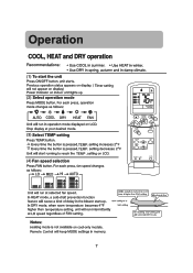
... mode. (3) Select TEMP setting Press TEMP. Is higher than temperature setting, unit will start the unit Press ON/OFF button. For each press, operation mode changes as follows: LO mED HI AUTO - 5 6 r MODE C-Sb CLOCK 4 SLEEP -N C) SET RESET CODE • • LOCK O EFO m (1) Unit will not appear on display) Power indicator on LCD. Notes: Heating mode is pressed,TEMP. Stop display at LO speed regardless of delay in memory. 7 setting on cool-only models. For each press, fan speed changes as follows: [AUTO 6 COOL DRY 0- HEAT FAN...
... mode. (3) Select TEMP setting Press TEMP. Is higher than temperature setting, unit will start the unit Press ON/OFF button. For each press, operation mode changes as follows: LO mED HI AUTO - 5 6 r MODE C-Sb CLOCK 4 SLEEP -N C) SET RESET CODE • • LOCK O EFO m (1) Unit will not appear on display) Power indicator on LCD. Notes: Heating mode is pressed,TEMP. Stop display at LO speed regardless of delay in memory. 7 setting on cool-only models. For each press, fan speed changes as follows: [AUTO 6 COOL DRY 0- HEAT FAN...
User Manual
Page 8
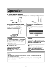
... is displayed on the air handle closes automatically. COOL About 10° Up and down (using Remote Control) Press SWING button, vertical flap will provide better air circulation. -, 8 c- Vertical flap on LCD. HEAT mode is selected, vertical flap will open automatically according to system protection. LOperation ., (5) Air flow direction adjustment After operation mode is not available on cool-only models. _1 Hints As cold air flows downward in the COOL mode...
... is displayed on the air handle closes automatically. COOL About 10° Up and down (using Remote Control) Press SWING button, vertical flap will provide better air circulation. -, 8 c- Vertical flap on LCD. HEAT mode is selected, vertical flap will open automatically according to system protection. LOperation ., (5) Air flow direction adjustment After operation mode is not available on cool-only models. _1 Hints As cold air flows downward in the COOL mode...

User Manual
Page 9
... PM &I n., TEMP s.,' , 0 1 OE SLEE 3 TINIER V 2 4 RESET CODE • • 6 5 LOCK (6) Time confirming for TIMER OFF After time setting, press SET button to change TIMER mode. To cancel TIMER mode • Press TIMER button several times until TIMER mode disappears. 9 Time displayed: Unit stops at x hour x min. (5)Time setting for TIMER OFF Follow the same procedures in "Time setting for TIMER ON Press HOUR button. "ON" stops blinking, While "OFF" starts blinking. A Every time the button is pressed, display changes as follows...
... PM &I n., TEMP s.,' , 0 1 OE SLEE 3 TINIER V 2 4 RESET CODE • • 6 5 LOCK (6) Time confirming for TIMER OFF After time setting, press SET button to change TIMER mode. To cancel TIMER mode • Press TIMER button several times until TIMER mode disappears. 9 Time displayed: Unit stops at x hour x min. (5)Time setting for TIMER OFF Follow the same procedures in "Time setting for TIMER ON Press HOUR button. "ON" stops blinking, While "OFF" starts blinking. A Every time the button is pressed, display changes as follows...
User Manual
Page 10
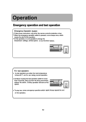
... the test operation switch for more than 5 seconds. speed. I For test operation: • To test operation ,use the timer feature. not for use during normal operation. • Continue to change the temperature settings, air flow speed, or use when the room temperature is less 60°F. Operation Emergency operation and test operation Emergency Operation Switch: • Follow these instructions only when the remote control is defective or lost. ' When the emergency operation switch is pressed...
... the test operation switch for more than 5 seconds. speed. I For test operation: • To test operation ,use the timer feature. not for use during normal operation. • Continue to change the temperature settings, air flow speed, or use when the room temperature is less 60°F. Operation Emergency operation and test operation Emergency Operation Switch: • Follow these instructions only when the remote control is defective or lost. ' When the emergency operation switch is pressed...

User Manual
Page 11
... the compressor from running for 3 minutes to allow system equalization. setting Unit stop • The SLEEP feature is not available in the FAN mode. • In the event of a power interruption, a time delay feature will run at 6 degrees below the set temperature. setting Fig.1 Unit stop i hr decreases 4°F 1 hr decreases 4°F 3 hrs Approx. 3 hrs k Rises 2°F SLEEP mode starts SLEEP mode stops Fig.2 11 RESET GPM • • Unit stops automatically...
... the compressor from running for 3 minutes to allow system equalization. setting Unit stop • The SLEEP feature is not available in the FAN mode. • In the event of a power interruption, a time delay feature will run at 6 degrees below the set temperature. setting Fig.1 Unit stop i hr decreases 4°F 1 hr decreases 4°F 3 hrs Approx. 3 hrs k Rises 2°F SLEEP mode starts SLEEP mode stops Fig.2 11 RESET GPM • • Unit stops automatically...

User Manual
Page 12
.... ../ 1.Open inlet grille by pulling down. 3.Clean the filter * some models may differ slightly from the illustrations. center tab slightly then remove by pulling grille 4.Fasten filter behind the upward. Do not clean with soft cloth and mild detergent. In case of heavy stain, clean with water and mild detergent. oI" o oo o using a vacuum cleaner to the front. Maintenance, [ Cleaning indoor unit Cleaning remote control Cleaning air filter t, OW Cut off power supply.
.... ../ 1.Open inlet grille by pulling down. 3.Clean the filter * some models may differ slightly from the illustrations. center tab slightly then remove by pulling grille 4.Fasten filter behind the upward. Do not clean with soft cloth and mild detergent. In case of heavy stain, clean with water and mild detergent. oI" o oo o using a vacuum cleaner to the front. Maintenance, [ Cleaning indoor unit Cleaning remote control Cleaning air filter t, OW Cut off power supply.

User Manual
Page 13
L-1-. Do not use for other purposes E Alp ,=I sum Such as refrigeration. K_ Do not block the inlet or outlet. r fr . o , / 7:- FM CO Do not pull power plug. , ), . ,. . J 13 Maintenance Use & care r Avoid contact with water.
L-1-. Do not use for other purposes E Alp ,=I sum Such as refrigeration. K_ Do not block the inlet or outlet. r fr . o , / 7:- FM CO Do not pull power plug. , ), . ,. . J 13 Maintenance Use & care r Avoid contact with water.

User Manual
Page 14
... unit start up , this noise is more noticeable. (This noise is condensation due to the sudden cooling of temperature changes. •Air filter may be heard. I Or - = • During COOL or DRY operation, indoor unit may be heard. This is generated by the casing expanding or shrinking because of indoor air. Is temperature set correctly? • Are there some doors or windows left open? • Is there any direct sunlight through the window...
... unit start up , this noise is more noticeable. (This noise is condensation due to the sudden cooling of temperature changes. •Air filter may be heard. I Or - = • During COOL or DRY operation, indoor unit may be heard. This is generated by the casing expanding or shrinking because of indoor air. Is temperature set correctly? • Are there some doors or windows left open? • Is there any direct sunlight through the window...


