
User Manual
Page 2
... refrigerant charge is the installer's responsibility to the air conditioner caused by the manufacturer) into, onto, or in accordance with National Codes. When the compressor shuts off due to thermostat operation or a power failure, this low can lead to Owner These instructions should be done by bleeding the high side only, it could ignite when it is located in a fire or an electric...
... refrigerant charge is the installer's responsibility to the air conditioner caused by the manufacturer) into, onto, or in accordance with National Codes. When the compressor shuts off due to thermostat operation or a power failure, this low can lead to Owner These instructions should be done by bleeding the high side only, it could ignite when it is located in a fire or an electric...

User Manual
Page 3
...-3-60 A Body style R Reserved Example: HR24D2VAR 1 TABLE OF CONTENT 1.Introduction 1 2.Nomenclature for future reference. 2.NOMENCLATURE FOR MODEL NUMBER H Brand symbol - Improper installation can result in (000) Btu/h D SEER designation. C: Air conditioner; General 5 6.2.Unit clearances 6 6.3.Refrigerant piping 6 6.4.Electrical wiring 11 7.System Startup 12 8.Operation 13 9.Miscellaneous 13 9.1.Replacement parts 13 9.2.Troubleshooting guide 13 9.3.Wiring diagram 13 1.INTRODUCTION This manual contains the installation and operating instructions for your new Heat Pump.
...-3-60 A Body style R Reserved Example: HR24D2VAR 1 TABLE OF CONTENT 1.Introduction 1 2.Nomenclature for future reference. 2.NOMENCLATURE FOR MODEL NUMBER H Brand symbol - Improper installation can result in (000) Btu/h D SEER designation. C: Air conditioner; General 5 6.2.Unit clearances 6 6.3.Refrigerant piping 6 6.4.Electrical wiring 11 7.System Startup 12 8.Operation 13 9.Miscellaneous 13 9.1.Replacement parts 13 9.2.Troubleshooting guide 13 9.3.Wiring diagram 13 1.INTRODUCTION This manual contains the installation and operating instructions for your new Heat Pump.
User Manual
Page 4
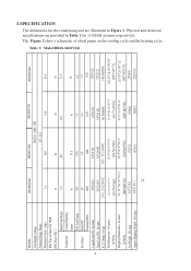
... Line OD - 3.SPECIFICATION The dimensions for 13 SEER systems respectively. Lbs (kg) Approx Shipping Weight - Table 1: Model:HR18-36D2VAR 24 2 MODEL: Unit Supply Voltage Normal Voltage Range Minimum Circuit Amps Max Fuse or Max CKT. Physical and electrical specifications are illustrated in Table 1 for the condensing unit are provided in Figure 1. BKR. (HACR per NEC ) Rated Load Amps Compressor Locked Running Amps Full Load Amps Fan Motor Rated HP Nominal...
... Line OD - 3.SPECIFICATION The dimensions for 13 SEER systems respectively. Lbs (kg) Approx Shipping Weight - Table 1: Model:HR18-36D2VAR 24 2 MODEL: Unit Supply Voltage Normal Voltage Range Minimum Circuit Amps Max Fuse or Max CKT. Physical and electrical specifications are illustrated in Table 1 for the condensing unit are provided in Figure 1. BKR. (HACR per NEC ) Rated Load Amps Compressor Locked Running Amps Full Load Amps Fan Motor Rated HP Nominal...

User Manual
Page 5
D Figure 1 W H Table 2: System Capacity cooling Outdoor Indoor Indoor fan ARI data of indoor Cooling Capacity with different outdoor temperature speed Capacity SEER CFM 80 85 90 95 100 105 110 115 HR18D2VAR HB2400VD1M20 M 17000 13...HR30D2VAR HB3600VD1M22 L 28000 13 1125 31640 30716 29680 28000 27580 27160 26740 26320 HR36D2VAR HB3600VD1M22 H 35000 13 1240 39550 38395 37100 35000 34475 33950 33425 32900 heating Outdoor Indoor Indoor fan ARI data of indoor Heating Capacity with different outdoor temperature speed Capacity HSPF CFM -10 0 10 20 30 40 50 60 HR18D2VAR ...
D Figure 1 W H Table 2: System Capacity cooling Outdoor Indoor Indoor fan ARI data of indoor Cooling Capacity with different outdoor temperature speed Capacity SEER CFM 80 85 90 95 100 105 110 115 HR18D2VAR HB2400VD1M20 M 17000 13...HR30D2VAR HB3600VD1M22 L 28000 13 1125 31640 30716 29680 28000 27580 27160 26740 26320 HR36D2VAR HB3600VD1M22 H 35000 13 1240 39550 38395 37100 35000 34475 33950 33425 32900 heating Outdoor Indoor Indoor fan ARI data of indoor Heating Capacity with different outdoor temperature speed Capacity HSPF CFM -10 0 10 20 30 40 50 60 HR18D2VAR ...
User Manual
Page 6
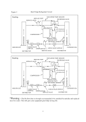
... 2 Cooling Heat Pump Refrigerant Circuit SERVICE PORT SERVICE VALVE DISCHARGE TEMP. SENSOR REVERSING VALVE COMPRESSOR HIGH PRESSURE SWITCH LOW PRESSURE ACCUMULATOR SERVICE PORT SERVICE PORT DEFROSED SENSOR EVAPORATOR CONDENSER INDOOR COIL CHECK VALVE CHECK VALVE ORIFICE OUTDOOR COIL ORIFICE DRIER(optional) DISTRIBUTOR SERVICE VALVE DISTRIBUTOR !Warning - The Bi-flow drier is strongly recommended to be installed by installer and replaced once two years. SENSOR REVERSING VALVE COMPRESSOR HIGH PRESSURE LOW PRESSURE ACCUMULATOR SERVICE PORT SERVICE PORT DEFROSED SENSOR...
... 2 Cooling Heat Pump Refrigerant Circuit SERVICE PORT SERVICE VALVE DISCHARGE TEMP. SENSOR REVERSING VALVE COMPRESSOR HIGH PRESSURE SWITCH LOW PRESSURE ACCUMULATOR SERVICE PORT SERVICE PORT DEFROSED SENSOR EVAPORATOR CONDENSER INDOOR COIL CHECK VALVE CHECK VALVE ORIFICE OUTDOOR COIL ORIFICE DRIER(optional) DISTRIBUTOR SERVICE VALVE DISTRIBUTOR !Warning - The Bi-flow drier is strongly recommended to be installed by installer and replaced once two years. SENSOR REVERSING VALVE COMPRESSOR HIGH PRESSURE LOW PRESSURE ACCUMULATOR SERVICE PORT SERVICE PORT DEFROSED SENSOR...

User Manual
Page 7
... occur or accumulate. 5 Don't locate unit in shipment. Inspect exterior of combustible gas leakage. If the unit is no risk of carton for outdoor installations. Regular cleaning and waxing of contaminants and help to shut off with water. Power supply and wiring. Location where external water drainage cannot collect around the unit. It is important to consult your local code authorities at roof level. Failure...
... occur or accumulate. 5 Don't locate unit in shipment. Inspect exterior of combustible gas leakage. If the unit is no risk of carton for outdoor installations. Regular cleaning and waxing of contaminants and help to shut off with water. Power supply and wiring. Location where external water drainage cannot collect around the unit. It is important to consult your local code authorities at roof level. Failure...
User Manual
Page 8
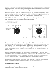
.... Refrigerant tube and electrical connections are to be located under an overhang, there should not be placed between the condenser and the slab. To prevent transmission of 10" clearance on the fin coil surface reducing the unit efficiency. 6.3.REFRIGERANT PIPING The refrigerant piping is given to the compressor and control box, allow 18" minimum clearance. A good material to deflect the warm discharge air...
.... Refrigerant tube and electrical connections are to be located under an overhang, there should not be placed between the condenser and the slab. To prevent transmission of 10" clearance on the fin coil surface reducing the unit efficiency. 6.3.REFRIGERANT PIPING The refrigerant piping is given to the compressor and control box, allow 18" minimum clearance. A good material to deflect the warm discharge air...

User Manual
Page 9
... suction line toward the compressor, approximately 1/2" for the liquid line to prevent liquid refrigerant flashing to be required. OUTDOOR UNIT INVERTED LOOP LIQUID LINE OUTDOOR UNIT OUTDOOR UNIT PITCH SUCTION LINE TOWARD OUTDOOR UNIT 1/2" FRO EVERY 10' OF LINE INDOOR UNIT ABOVE OR LEVEL TO OUTDOOR UNIT LIQUID LINE A INDOOR UNIT 6' ADDITIONAL SUCTION LINE OIL TRAP FOR EACH 20 FOOT RISE OF PIPE 70' MAX. Generally 3/8" wall thickness of line. To...
... suction line toward the compressor, approximately 1/2" for the liquid line to prevent liquid refrigerant flashing to be required. OUTDOOR UNIT INVERTED LOOP LIQUID LINE OUTDOOR UNIT OUTDOOR UNIT PITCH SUCTION LINE TOWARD OUTDOOR UNIT 1/2" FRO EVERY 10' OF LINE INDOOR UNIT ABOVE OR LEVEL TO OUTDOOR UNIT LIQUID LINE A INDOOR UNIT 6' ADDITIONAL SUCTION LINE OIL TRAP FOR EACH 20 FOOT RISE OF PIPE 70' MAX. Generally 3/8" wall thickness of line. To...

User Manual
Page 10
... any combination of the unit size and the maximum refrigerant line length. Heat Pumps are illustrated in the accessory bag. Don't forget to remove pressure. ! To ensure good oil return to contain the charge within the unit. CAUTION - Per foot. Vertical Separation between Indoor and Outdoor Units Maximum allowable vertical separations between indoor and outdoor units are charged with refrigerant. CAUTION - Instructions on the liquid line...
... any combination of the unit size and the maximum refrigerant line length. Heat Pumps are illustrated in the accessory bag. Don't forget to remove pressure. ! To ensure good oil return to contain the charge within the unit. CAUTION - Per foot. Vertical Separation between Indoor and Outdoor Units Maximum allowable vertical separations between indoor and outdoor units are charged with refrigerant. CAUTION - Instructions on the liquid line...

User Manual
Page 11
... with the outdoor unit. Table 4 outdoor model HR18D2VAR HR24D2VAR HR30D2VAR HR36D2VAR Fixed orifice size indoor model HB2400VD1M20 HB2400VD1M20 HB3600VD1M22 HB3600VD1M22 orifice size 057 065 071 078 9 This prevents flux from getting into the system. 4.Remove the cap and Schrader valve core from the service port to prevent contamination from entering the system. 2.Make sure that both refrigerant stop valves at the outdoor unit are closed...
... with the outdoor unit. Table 4 outdoor model HR18D2VAR HR24D2VAR HR30D2VAR HR36D2VAR Fixed orifice size indoor model HB2400VD1M20 HB2400VD1M20 HB3600VD1M22 HB3600VD1M22 orifice size 057 065 071 078 9 This prevents flux from getting into the system. 4.Remove the cap and Schrader valve core from the service port to prevent contamination from entering the system. 2.Make sure that both refrigerant stop valves at the outdoor unit are closed...

User Manual
Page 12
... high condensing pressure, which increases power consumption and reduces performance. If the refrigerant needs to be removed from a system to the vacuum pump and wait 15 minutes. Proper evacuation assures a dry, uncontaminated system. WARNING - Air in a very short time. The presence of the desired comfort conditions. ! Evacuation All new installations must be evacuated to a deep vacuum in order that the outdoor unit and indoor coil...
... high condensing pressure, which increases power consumption and reduces performance. If the refrigerant needs to be removed from a system to the vacuum pump and wait 15 minutes. Proper evacuation assures a dry, uncontaminated system. WARNING - Air in a very short time. The presence of the desired comfort conditions. ! Evacuation All new installations must be evacuated to a deep vacuum in order that the outdoor unit and indoor coil...
User Manual
Page 14
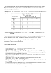
... cooling mode. 5.The compressor, indoor blower, and outdoor fan should now be running . 9.If unit operates properly on the wiring diagram. 7.SYSTEM STARTUP 1.Turn thermostat to startup. 12 Indoor blower should stop 90 seconds later. 7.Turn system switch to "Heat" and fan switch to "AUTO". The blower should run in the right direction. 4.Turn fan switch to "Auto" . 8.Slowly raise the heating temperature setting. The condensing unit control wiring requires a 24 Volt minimum, 25 VA service from the indoor transformer as a function of proper size electrical service...
... cooling mode. 5.The compressor, indoor blower, and outdoor fan should now be running . 9.If unit operates properly on the wiring diagram. 7.SYSTEM STARTUP 1.Turn thermostat to startup. 12 Indoor blower should stop 90 seconds later. 7.Turn system switch to "Heat" and fan switch to "AUTO". The blower should run in the right direction. 4.Turn fan switch to "Auto" . 8.Slowly raise the heating temperature setting. The condensing unit control wiring requires a 24 Volt minimum, 25 VA service from the indoor transformer as a function of proper size electrical service...

User Manual
Page 15
... cause the compressor to both the indoor and outdoor units. Failure to reset. Make sure overload has had time to make sure the unit defrosts properly. 12.Check the refrigerant charge (see Instructions under "Charging the System"). 13.Replace service port caps. Poor electrical service can cause electrical shock resulting in overloads or blow fuses. Wiring Diagram Refer to the troubleshooting guide (Table 7) included in this manual.(P14) 9.3. WARNING - Replacement Parts Contact...
... cause the compressor to both the indoor and outdoor units. Failure to reset. Make sure overload has had time to make sure the unit defrosts properly. 12.Check the refrigerant charge (see Instructions under "Charging the System"). 13.Replace service port caps. Poor electrical service can cause electrical shock resulting in overloads or blow fuses. Wiring Diagram Refer to the troubleshooting guide (Table 7) included in this manual.(P14) 9.3. WARNING - Replacement Parts Contact...

User Manual
Page 16
... reset. should be within 10% of rating plate volts when unit is running pressures Air, non-condensibles or moisture in liquid line, High head - High Refrigerant overcharge or normal vapor Condenser fan not running . Replace - Recover refrigerant, evacuate & recharge 14 Incorrect thermostat setting Set thermostat correctly No cooling/heating Defective contactor Check for blockage. Water on floor or in furnace Blocked condensate drain and "P" trap Remove blockage Run or start kit components At compressor...
... reset. should be within 10% of rating plate volts when unit is running pressures Air, non-condensibles or moisture in liquid line, High head - High Refrigerant overcharge or normal vapor Condenser fan not running . Replace - Recover refrigerant, evacuate & recharge 14 Incorrect thermostat setting Set thermostat correctly No cooling/heating Defective contactor Check for blockage. Water on floor or in furnace Blocked condensate drain and "P" trap Remove blockage Run or start kit components At compressor...


