
User Manual
Page 2
... pressurized refrigerant and oil mixture could result in fire, electrical shock, property damage, personal injury or death. Message to Owner These instructions should be done by the attachment or use of unauthorized components, accessories or devices may adversely affect the operation of the air conditioner and may vary due to qualified, licensed service personnel for equipment installed in violation of new laws...
... pressurized refrigerant and oil mixture could result in fire, electrical shock, property damage, personal injury or death. Message to Owner These instructions should be done by the attachment or use of unauthorized components, accessories or devices may adversely affect the operation of the air conditioner and may vary due to qualified, licensed service personnel for equipment installed in violation of new laws...

User Manual
Page 3
...Air conditioner; The owner should retain this manual for Model Number 1 3.Specification 2 4.Unit Inspection 5 5.Equipment Protection From Environment 5 6.Installation 5 6.1. D=13, E=14 2 Design series. 2 - 2nd Generation V Electric: V=208/230-1-60; TABLE OF CONTENT 1.Introduction 1 2.Nomenclature for future reference. 2.NOMENCLATURE FOR MODEL NUMBER H Brand symbol - General 5 6.2.Unit clearances 6 6.3.Refrigerant piping 6 6.4.Electrical wiring 11 7.System Startup 12 8.Operation 13 9.Miscellaneous 13 9.1.Replacement parts 13 9.2.Troubleshooting guide 13 9.3.Wiring diagram...
...Air conditioner; The owner should retain this manual for Model Number 1 3.Specification 2 4.Unit Inspection 5 5.Equipment Protection From Environment 5 6.Installation 5 6.1. D=13, E=14 2 Design series. 2 - 2nd Generation V Electric: V=208/230-1-60; TABLE OF CONTENT 1.Introduction 1 2.Nomenclature for future reference. 2.NOMENCLATURE FOR MODEL NUMBER H Brand symbol - General 5 6.2.Unit clearances 6 6.3.Refrigerant piping 6 6.4.Electrical wiring 11 7.System Startup 12 8.Operation 13 9.Miscellaneous 13 9.1.Replacement parts 13 9.2.Troubleshooting guide 13 9.3.Wiring diagram...
User Manual
Page 4
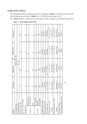
Table 1: Model:HR18-36D2VAR 24 2 MODEL: Unit Supply Voltage Normal Voltage Range Minimum Circuit Amps Max Fuse or Max CKT. Lbs (kg) Approx Shipping Weight - BKR. (HACR per NEC ) Rated Load Amps Compressor Locked Running Amps Full Load Amps Fan Motor Rated HP Nominal RPM Liquid Line OD - In (mm) Vapor Line OD - In (mm) W*D*H Shipping Dimensions - In (mm) R-22 Charge -Oz (g) Net Dimensions - In (mm) W*D*H Net...
Table 1: Model:HR18-36D2VAR 24 2 MODEL: Unit Supply Voltage Normal Voltage Range Minimum Circuit Amps Max Fuse or Max CKT. Lbs (kg) Approx Shipping Weight - BKR. (HACR per NEC ) Rated Load Amps Compressor Locked Running Amps Full Load Amps Fan Motor Rated HP Nominal RPM Liquid Line OD - In (mm) Vapor Line OD - In (mm) W*D*H Shipping Dimensions - In (mm) R-22 Charge -Oz (g) Net Dimensions - In (mm) W*D*H Net...

User Manual
Page 5
... 13 900 25425 24683 23850 22500 22162.5 21825 21488 21150 HR30D2VAR HB3600VD1M22 L 28000 13 1125 31640 30716 29680 28000 27580 27160 26740 26320 HR36D2VAR HB3600VD1M22 H 35000 13 1240 39550 38395 37100 35000 34475 33950 33425 32900 heating Outdoor Indoor Indoor fan ARI data of indoor Heating Capacity with different outdoor temperature speed Capacity HSPF CFM -10 0 10 20 30 40...
... 13 900 25425 24683 23850 22500 22162.5 21825 21488 21150 HR30D2VAR HB3600VD1M22 L 28000 13 1125 31640 30716 29680 28000 27580 27160 26740 26320 HR36D2VAR HB3600VD1M22 H 35000 13 1240 39550 38395 37100 35000 34475 33950 33425 32900 heating Outdoor Indoor Indoor fan ARI data of indoor Heating Capacity with different outdoor temperature speed Capacity HSPF CFM -10 0 10 20 30 40...
User Manual
Page 6
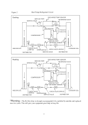
... will give your equipment great help in long life. 4 SENSOR REVERSING VALVE COMPRESSOR HIGH PRESSURE LOW PRESSURE ACCUMULATOR SERVICE PORT SERVICE PORT DEFROSED SENSOR CONDENSER EVAPORATOR INDOOR COIL CHECK VALVE ORIFICE DRIER(optional) CHECK VALVE ORIFICE DISTRIBUTOR SERVICE VALVE DISTRIBUTOR OUTDOOR COIL Heating SERVICE PORT SERVICE VALVE DISCHARGE TEMP. The Bi-flow drier is strongly recommended to be installed by installer and replaced once two years. Figure 2 Cooling Heat Pump Refrigerant Circuit SERVICE PORT SERVICE VALVE DISCHARGE...
... will give your equipment great help in long life. 4 SENSOR REVERSING VALVE COMPRESSOR HIGH PRESSURE LOW PRESSURE ACCUMULATOR SERVICE PORT SERVICE PORT DEFROSED SENSOR CONDENSER EVAPORATOR INDOOR COIL CHECK VALVE ORIFICE DRIER(optional) CHECK VALVE ORIFICE DISTRIBUTOR SERVICE VALVE DISTRIBUTOR OUTDOOR COIL Heating SERVICE PORT SERVICE VALVE DISCHARGE TEMP. The Bi-flow drier is strongly recommended to be installed by installer and replaced once two years. Figure 2 Cooling Heat Pump Refrigerant Circuit SERVICE PORT SERVICE VALVE DISCHARGE...

User Manual
Page 7
... some protection. It is frequent cleaning, maintenance and minimal exposure to both the indoor and outdoor units. Location for minimum noise, where operating sounds will reduce the buildup of supporting members. Unpack carefully. Avoid having lawn sprinkler heads spray directly on the side of rough handling in seacoast areas, sulphur or chlorine from lawn watering systems and various chemical contaminants from...
... some protection. It is frequent cleaning, maintenance and minimal exposure to both the indoor and outdoor units. Location for minimum noise, where operating sounds will reduce the buildup of supporting members. Unpack carefully. Avoid having lawn sprinkler heads spray directly on the side of rough handling in seacoast areas, sulphur or chlorine from lawn watering systems and various chemical contaminants from...
User Manual
Page 8
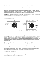
... air conditioning system. A good material to use is given to the tubing or wiring. The condensing unit contains moving parts and can bear the weight of the roof. Service Access 18" Min. Condenser air enters from back wall with subsequent damage to the weather-tight integrity of the unit. Air discharges upward from the service access area. Refrigerant tube and electrical connections are made to the compressor...
... air conditioning system. A good material to use is given to the tubing or wiring. The condensing unit contains moving parts and can bear the weight of the roof. Service Access 18" Min. Condenser air enters from back wall with subsequent damage to the weather-tight integrity of the unit. Air discharges upward from the service access area. Refrigerant tube and electrical connections are made to the compressor...

User Manual
Page 9
... condensation from the tubing. Do not kink or twist the tubing. Use a closed cell insulation to directly contact the tubing. Refrigerant piping should not be as short as this limits access to and during installation. OUTDOOR UNIT INVERTED LOOP LIQUID LINE OUTDOOR UNIT OUTDOOR UNIT PITCH SUCTION LINE TOWARD OUTDOOR UNIT 1/2" FRO EVERY 10' OF LINE INDOOR UNIT ABOVE OR LEVEL TO OUTDOOR UNIT LIQUID LINE A INDOOR UNIT 6' ADDITIONAL SUCTION LINE OIL...
... condensation from the tubing. Do not kink or twist the tubing. Use a closed cell insulation to directly contact the tubing. Refrigerant piping should not be as short as this limits access to and during installation. OUTDOOR UNIT INVERTED LOOP LIQUID LINE OUTDOOR UNIT OUTDOOR UNIT PITCH SUCTION LINE TOWARD OUTDOOR UNIT 1/2" FRO EVERY 10' OF LINE INDOOR UNIT ABOVE OR LEVEL TO OUTDOOR UNIT LIQUID LINE A INDOOR UNIT 6' ADDITIONAL SUCTION LINE OIL...

User Manual
Page 10
... ! Heat Pumps are closed to the compressor when the indoor unit is below the outdoor unit (Figure 4-A), and 50' when the indoor unit is on the field tubing connections and valve opening procedure are illustrated in the accessory bag. Don't forget to remove pressure. ! CAUTION - Use extreme caution in Figure 4-A. The piston is sufficient for any combination of the unit size and the maximum refrigerant...
... ! Heat Pumps are closed to the compressor when the indoor unit is below the outdoor unit (Figure 4-A), and 50' when the indoor unit is on the field tubing connections and valve opening procedure are illustrated in the accessory bag. Don't forget to remove pressure. ! CAUTION - Use extreme caution in Figure 4-A. The piston is sufficient for any combination of the unit size and the maximum refrigerant...

User Manual
Page 11
... lines with the outdoor unit. Table 4 outdoor model HR18D2VAR HR24D2VAR HR30D2VAR HR36D2VAR Fixed orifice size indoor model HB2400VD1M20 HB2400VD1M20 HB3600VD1M22 HB3600VD1M22 orifice size 057 065 071 078 9 If a leak is found, repair it is round and free of interconnecting tubing. Clean the tubing to prevent contamination from the service port to cool the joint. Reinstall the Schrader core in the valve, if removed for leaks at all...
... lines with the outdoor unit. Table 4 outdoor model HR18D2VAR HR24D2VAR HR30D2VAR HR36D2VAR Fixed orifice size indoor model HB2400VD1M20 HB2400VD1M20 HB3600VD1M22 HB3600VD1M22 orifice size 057 065 071 078 9 If a leak is found, repair it is round and free of interconnecting tubing. Clean the tubing to prevent contamination from the service port to cool the joint. Reinstall the Schrader core in the valve, if removed for leaks at all...

User Manual
Page 12
... the charge inside, always use a recovery or recycling device. ! If the refrigerant needs to be removed from a system to charging the system. Evacuation All new installations must be evacuated to a deep vacuum in order that the outdoor unit and indoor coil must be an approved match per the unit specification. Do not vent refrigerant to the vacuum pump and stop pump. 4.When sure of 30 minutes. Repair any leaks found...
... the charge inside, always use a recovery or recycling device. ! If the refrigerant needs to be removed from a system to charging the system. Evacuation All new installations must be evacuated to a deep vacuum in order that the outdoor unit and indoor coil must be an approved match per the unit specification. Do not vent refrigerant to the vacuum pump and stop pump. 4.When sure of 30 minutes. Repair any leaks found...
User Manual
Page 14
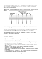
... Wire Size Based on power supply at disconnect switch. 2.Turn temperature setting as high as shown on the wiring diagram. 7.SYSTEM STARTUP 1.Turn thermostat to the "Auto" position. The condensing unit control wiring requires a 24 Volt minimum, 25 VA service from the indoor transformer as it is supplied by the unit. 6.Turn the fan switch to "OFF", turn temperature setting below room temperature. Make sure cool air is running in cooling mode. 5.The compressor, indoor blower, and outdoor fan should now be running . 9.If unit operates properly...
... Wire Size Based on power supply at disconnect switch. 2.Turn temperature setting as high as shown on the wiring diagram. 7.SYSTEM STARTUP 1.Turn thermostat to the "Auto" position. The condensing unit control wiring requires a 24 Volt minimum, 25 VA service from the indoor transformer as it is supplied by the unit. 6.Turn the fan switch to "OFF", turn temperature setting below room temperature. Make sure cool air is running in cooling mode. 5.The compressor, indoor blower, and outdoor fan should now be running . 9.If unit operates properly...

User Manual
Page 15
... sheet metal rattles. 15.Instruct the owner on operation and maintenance. Disconnect power to stop on an automatic open overload device or blow a fuse. Service port cores are operated without waiting 5 minutes. The compressor has an internal overload protector. Wiring Diagram Refer to the appropriate wiring diagram included in this manual.(P14) 9.3. Disconnect all electrical power to the unit before restarting to allow equalization of 5 minutes before servicing. Leave this overload to reset. Replacement Parts...
... sheet metal rattles. 15.Instruct the owner on operation and maintenance. Disconnect power to stop on an automatic open overload device or blow a fuse. Service port cores are operated without waiting 5 minutes. The compressor has an internal overload protector. Wiring Diagram Refer to the appropriate wiring diagram included in this manual.(P14) 9.3. Disconnect all electrical power to the unit before restarting to allow equalization of 5 minutes before servicing. Leave this overload to reset. Replacement Parts...

User Manual
Page 16
... all connections. Open circuit breaker of rating plate volts when unit is running . Interconnecting low voltage wiring damage Replace thermostat wiring Dirty filters Clean & replace Indoor air blockage Check supply registers and return grills for correct voltage Add refrigerant Increase blower speed or reduce restriction - Low metering device or filter drier vapor pressures Flowrator piston size too small Incorrect capillary tubes Blocked outdoor coil High head - cool Low evaporator airflow compressor - Wait...
... all connections. Open circuit breaker of rating plate volts when unit is running . Interconnecting low voltage wiring damage Replace thermostat wiring Dirty filters Clean & replace Indoor air blockage Check supply registers and return grills for correct voltage Add refrigerant Increase blower speed or reduce restriction - Low metering device or filter drier vapor pressures Flowrator piston size too small Incorrect capillary tubes Blocked outdoor coil High head - cool Low evaporator airflow compressor - Wait...


