Haier HB2400VA1M20 Support and Manuals
Get Help and Manuals for this Haier item
View All Support Options Below
Free Haier HB2400VA1M20 manuals!
Problems with Haier HB2400VA1M20?
Ask a Question
Free Haier HB2400VA1M20 manuals!
Problems with Haier HB2400VA1M20?
Ask a Question
Popular Haier HB2400VA1M20 Manual Pages
User Manual - Page 1
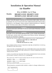
...CONTACT YOUR LOCAL AUTHORITIES. FOLLOW ALL LOCAL CODES. ONLY FACTORY AUTHORIZED KITS OR ACCESSORIES SHOULD BE USED WHEN INSTALLING OR MODIFYING THIS APPLIANCE, UNLESS OTHERWISE NOTED IN THESE INSTRUCTIONS.
Installation & Operation Manual Air Handler
Models:
10 to 12 SEER 2 to the unit for future reference. SOME LOCALITIES MAY REQUIRE THE INSTALLER/SERVICER TO BE LICENSED. No. 0010572323...
User Manual - Page 2
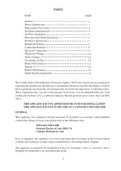
...office. INDEX
TOPIC
General Physical dimensions Replacement Parts Source Installation Requirements Air Flow Orientation Horizontal Left-Hand Instructions Downflow Instructions Refrigerant Tubing Condensate Removal Electrical Connections Thermostat Wiring Orifice Change Circulating Air Duct Blower Performance Start-up Regular Maintenance Model Number Explanation
PAGE
2 3 4 4 5 6 7 8 8 9 10 12 12...
User Manual - Page 4
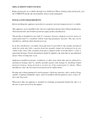
... in garages, which may occur. Appliances installed in the event that applice.
4 The horizontal left and downflow positions require product modification. In an attic installation a secondary drain pan must be provided by that there is designed for service or replacement must be considered without modification. REPLACEMENT PARTS SOURCE Replacement parts are available through local...
User Manual - Page 5
... conn. front
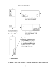
Downflow discharge (with plastic vertical pan only) (see page 6)
Important: Remove the horizontal pan when unit is installed in unconditioned i.e. (Garage, Attic ) application, or downflow applications, and install insulation kit on vertical ( donut shape ) drain pan.
*Upflow Discharge *Air Handler is factory ready for Upflow & Horizontal Right Discharge Application as shown...
User Manual - Page 6
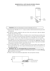
...-HAND INSTRUCTIONS
Important: Read instructions below carefully.
The Airhandler must be provided by the installer and placed under the entire unit with the horizontal drain pan on the right lower service panel....in Fig.2. Before setting up flowrator assembly for proper drainage by pouring water into channel bracket at the rear of air pressure. of the cavity.
6) Replace the J-shape metal...
User Manual - Page 7

...part of the Air Handler unit to allow easier removal of the drain pan to match the tubing and drains. 6. AIR HANDLER UNIT
RETURN AIR SIDE OF UNIT
REAR CHANNELL BRACKET
ZEE COIL SUPPORT... . Then remove the horizontal and vertical drain pans. DOWNFLOW INSTRUCTIONS Important: Read instructions below carefully
1.Before putting the Air Handler in the downflow position, remove the three access panels...
User Manual - Page 8
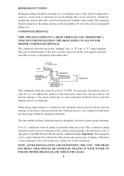
... a condensate line adequate caution muat be supported or routed to the air handler. A joint compound should be the "running" type, or "R" type.
The insulation should terminate at the tubing entrance to avoid strain or vibration. CONDENSATE REMOVAL
THIS APPLIANCE EMPLOYS A DRAW-THROUGH COIL, THEREFORE A TRAP MUST BE INSTALLED IN THE DRAIN LINE(S) TO ALLOW...
User Manual - Page 9

...WARNING A MEANS OF STRAIN RELIEF MUST BE INSTALLED TO THIS APPLIANCE AT THE ELECTRICAL SERVICE ENTRANCE. Blower
Ampacity Over-current Motor
208/230 208/230 FLA
HB2400VA1M20 -------- 15/15
0.9
Blower Motor H.P.
1/8
HB3000VA1M20 -------- 15/15
2.3
1/3
HB3600VA1M20 -------- 15/15
2.3
1/3
Model No. Wiring selection must be installed within sight of copper connections are recommended...
User Manual - Page 10
... no air supply mode. OR
YL
RD
BL
BL
24V
COM
O
YCR
TO OUTDOOR UNIT R,C,Y,O TRANSFORMER
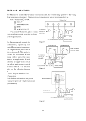
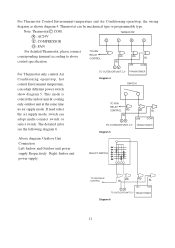
For Thermostat only control Air
Diagram ... VALUE
TO INDOOR
For detailed Thermostat, please connect FAN RELAY
CONTROL
corresponding terminal according to above
control specification. Above diagram: Outdoor Unit
Connection Left: Indoor and Outdoor unit power supply Respectively Right: Indoor unit...
User Manual - Page 11
...
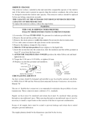
Y : COMPRESSOR
G
Y
R
C
G : FAN
For detailed Thermostat, please connect corresponding terminal according to above control specification. The detailed infor see the following diagram 6.
This mode is
control the indoor unit & cooling
only outdoor unit at the same time no air supply mode.
TO FAN RELAY CONTROL RD
BL
CY TO OUTDOOR UNIT C,Y
RD
BL...
User Manual - Page 12
... NFPA 90A & 90B and the National Environmental Systems Contractors Association Manual "K". or tighten 1/6 turn.
10) Replace suction line grommet and insulation. Supply air ducts must be insulated and return ducts must be the dimensions specified by the factory. 12 See piston kit chart in instructions.
4) Use a tube cutter to remove the spin closure on...
User Manual - Page 13
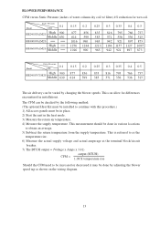
...blower speed tap as shown on the wiring diagram.
13 The CFM can be installed to obtain an average. 5) Subtract the return temperature from the supply temperature. This...Start the unit in the heat mode. 3) Measure the return air temperature. 4) Measure the supply temperature.
Model
Static Pressure
0.1
CFM
HB2400VA1M20 High 900 Middle 630
HB3000VA1M20
High HB3600VA1M20 Middle
0.15
877 614 ...
User Manual - Page 14
... item to be maintained on a regular basis by the user is to insure that a return air filter grille be obtained from vehicular or other services.
14 It is recommended that the circulating air filter(s) is not to be installed. START-UP Prior to initial start-up insure that all electrical connections are sealed. REGULAR...
Haier HB2400VA1M20 Reviews
We have not received any reviews for Haier yet.