User Manual
Page 1
... PRODUCING DEVICES (i.e. MODEL # HB 00VA1M20 MODEL # HB 00VC1M20 INSTALLATION DATE The information contained in this booklet is subject to change without notice. SOME LOCALITIES MAY REQUIRE THE INSTALLER/SERVICER TO BE LICENSED. FOLLOW ALL LOCAL CODES. ONLY FACTORY AUTHORIZED KITS OR ACCESSORIES SHOULD BE USED WHEN INSTALLING OR MODIFYING THIS APPLIANCE, UNLESS OTHERWISE NOTED IN THESE INSTRUCTIONS. AUTOMOBILE, SPACE HEATER, WATER HEATER,ETC.) INSURE...
... PRODUCING DEVICES (i.e. MODEL # HB 00VA1M20 MODEL # HB 00VC1M20 INSTALLATION DATE The information contained in this booklet is subject to change without notice. SOME LOCALITIES MAY REQUIRE THE INSTALLER/SERVICER TO BE LICENSED. FOLLOW ALL LOCAL CODES. ONLY FACTORY AUTHORIZED KITS OR ACCESSORIES SHOULD BE USED WHEN INSTALLING OR MODIFYING THIS APPLIANCE, UNLESS OTHERWISE NOTED IN THESE INSTRUCTIONS. AUTOMOBILE, SPACE HEATER, WATER HEATER,ETC.) INSURE...
User Manual
Page 2
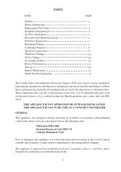
... NOT APPROVED FOR OUTDOOR INSTALLATION THIS APPLIANCE IS NOT TO BE USED AS A CONSTRUCTION HEATER GENERAL This appliance was tested and inspected for connection to the imposition of substantial fines. INDEX TOPIC General Physical dimensions Replacement Parts Source Installation Requirements Air Flow Orientation Horizontal Left-Hand Instructions Downflow Instructions Refrigerant Tubing Condensate Removal Electrical Connections Thermostat Wiring Orifice Change Circulating Air Duct Blower Performance Start-up Regular Maintenance Model Number Explanation PAGE 2 3 4 4 5 6 7 8 8 9 10...
... NOT APPROVED FOR OUTDOOR INSTALLATION THIS APPLIANCE IS NOT TO BE USED AS A CONSTRUCTION HEATER GENERAL This appliance was tested and inspected for connection to the imposition of substantial fines. INDEX TOPIC General Physical dimensions Replacement Parts Source Installation Requirements Air Flow Orientation Horizontal Left-Hand Instructions Downflow Instructions Refrigerant Tubing Condensate Removal Electrical Connections Thermostat Wiring Orifice Change Circulating Air Duct Blower Performance Start-up Regular Maintenance Model Number Explanation PAGE 2 3 4 4 5 6 7 8 8 9 10...
User Manual
Page 4
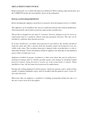
... a leak or main drain blockage. REPLACEMENT PARTS SOURCE Replacement parts are available through local distributors.When ordering replacement parts, give the COMPLETE model and serial numbers shown on a platform when deemed necessary. This unit can be subjected to the owner. Appliances installed in garages, warehouses or other areas where they may be installed in the vertical or right horizontal position without removing permanent structure. When installed on...
... a leak or main drain blockage. REPLACEMENT PARTS SOURCE Replacement parts are available through local distributors.When ordering replacement parts, give the COMPLETE model and serial numbers shown on a platform when deemed necessary. This unit can be subjected to the owner. Appliances installed in garages, warehouses or other areas where they may be installed in the vertical or right horizontal position without removing permanent structure. When installed on...
User Manual
Page 5
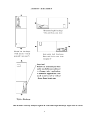
front (see page 7) Horizontal Left Discharge Tube and Drain conn. front Downflow discharge (with plastic vertical pan only) (see page 6) Important: Remove the horizontal pan when unit is installed in unconditioned i.e. (Garage, Attic ) application, or downflow applications, and install insulation kit on vertical ( donut shape ) drain pan. *Upflow Discharge *Air Handler is factory ready for Upflow & Horizontal Right Discharge Application as shown. 5 AIR FLOW ORIENTATION *Horizontal Right Discharge Tube and Drain conn.
front (see page 7) Horizontal Left Discharge Tube and Drain conn. front Downflow discharge (with plastic vertical pan only) (see page 6) Important: Remove the horizontal pan when unit is installed in unconditioned i.e. (Garage, Attic ) application, or downflow applications, and install insulation kit on vertical ( donut shape ) drain pan. *Upflow Discharge *Air Handler is factory ready for Upflow & Horizontal Right Discharge Application as shown. 5 AIR FLOW ORIENTATION *Horizontal Right Discharge Tube and Drain conn.
User Manual
Page 6
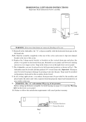
... INSTRUCTIONS Important: Read instructions below carefully. Reinstall access panels and flowrator making sure not to the user. 9) WARNING: The "A" coil contains 150 p.s.i.g. Plastic Drain cover Fig.1 oval gasket WARNING: If incorrect knockouts are removed, flooding will cancel product warranty. The Airhandler must be leveled and then pitched 1/4" toward drain side. Traps must be installed on the primary drain and on horizontal drain pan. Fig.2 6 Air...
... INSTRUCTIONS Important: Read instructions below carefully. Reinstall access panels and flowrator making sure not to the user. 9) WARNING: The "A" coil contains 150 p.s.i.g. Plastic Drain cover Fig.1 oval gasket WARNING: If incorrect knockouts are removed, flooding will cancel product warranty. The Airhandler must be leveled and then pitched 1/4" toward drain side. Traps must be installed on the primary drain and on horizontal drain pan. Fig.2 6 Air...

User Manual
Page 7
... the Warning label on the bottom of coils that are shipped with a check flowrator for use with either cooling or heat pump outdoor section which include (1) tie bracket (1) rear channel bracket, (2) zee coil supports, (2) stiffener brackets, and (2) 3" 2 flat insulation retaining brackets. Fig.3 3" FLAT INSULATION RETAINER (both sides) 7 AIR HANDLER UNIT RETURN AIR SIDE OF UNIT REAR CHANNELL BRACKET ZEE COIL SUPPORT BRACKET COIL RETAINING BRACKET TIE BRACKET NOTE: THE FIL TER PROVISION IS...
... the Warning label on the bottom of coils that are shipped with a check flowrator for use with either cooling or heat pump outdoor section which include (1) tie bracket (1) rear channel bracket, (2) zee coil supports, (2) stiffener brackets, and (2) 3" 2 flat insulation retaining brackets. Fig.3 3" FLAT INSULATION RETAINER (both sides) 7 AIR HANDLER UNIT RETURN AIR SIDE OF UNIT REAR CHANNELL BRACKET ZEE COIL SUPPORT BRACKET COIL RETAINING BRACKET TIE BRACKET NOTE: THE FIL TER PROVISION IS...
User Manual
Page 8
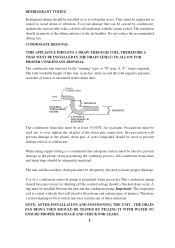
... the recommended tubing size. The condensate trap must be installed between the unit and the condensate pump. All condensate drain lines and drain traps should a blocked drain occur. A trap must not be the "running" type, or "R" type. NOTE: AFTER INSTALLATION AND POSITIONING THE UNIT , THE DRAIN PAN BEING USED SHOULD BE TESTED BY FILLING IT WITH WATER TO ENSURE PROPER DRAINAGE AND CHECK FOR LEAKS. 8 REFRIGERANT TUBING Refrigerant tubing should be...
... the recommended tubing size. The condensate trap must be installed between the unit and the condensate pump. All condensate drain lines and drain traps should a blocked drain occur. A trap must not be the "running" type, or "R" type. NOTE: AFTER INSTALLATION AND POSITIONING THE UNIT , THE DRAIN PAN BEING USED SHOULD BE TESTED BY FILLING IT WITH WATER TO ENSURE PROPER DRAINAGE AND CHECK FOR LEAKS. 8 REFRIGERANT TUBING Refrigerant tubing should be...

User Manual
Page 9
... inside the control box (see UL 1995, section 37.9). The use of the unit, when required by code. Min. Max. ELECTRICAL CONNECTIONS The required electrical power supply information is located on the series and rating plate on the air handler. When an optional heat kit is only for all electrical connections. Model No. Blower Ampacity Over-current Motor 208/230 208/230 FLA HB2400VA1M20 -------- 15/15 0.9 Blower Motor...
... inside the control box (see UL 1995, section 37.9). The use of the unit, when required by code. Min. Max. ELECTRICAL CONNECTIONS The required electrical power supply information is located on the series and rating plate on the air handler. When an optional heat kit is only for all electrical connections. Model No. Blower Ampacity Over-current Motor 208/230 208/230 FLA HB2400VA1M20 -------- 15/15 0.9 Blower Motor...
User Manual
Page 10
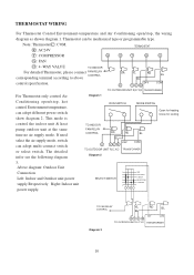
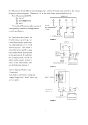
R : AC24V TERMOSTAT Y : COMPRESSOR G O Y R C G : FAN O : 4 -WAY VALUE TO INDOOR For detailed Thermostat, please connect FAN RELAY CONTROL corresponding terminal according to above control specification. If need select the air supply mode, switch can be mechanical type or programmable type. Note: Thermostat C : COM. This mode is RUN SWITCH MODE SWITCH Open for heating Close for cooling control the indoor unit & heat pump outdoor unit at the same time no air supply mode. The detailed infor see the following diagram TO INDOOR FAN RELAY CONTROL RD RD BL BL...
R : AC24V TERMOSTAT Y : COMPRESSOR G O Y R C G : FAN O : 4 -WAY VALUE TO INDOOR For detailed Thermostat, please connect FAN RELAY CONTROL corresponding terminal according to above control specification. If need select the air supply mode, switch can be mechanical type or programmable type. Note: Thermostat C : COM. This mode is RUN SWITCH MODE SWITCH Open for heating Close for cooling control the indoor unit & heat pump outdoor unit at the same time no air supply mode. The detailed infor see the following diagram TO INDOOR FAN RELAY CONTROL RD RD BL BL...
User Manual
Page 11
... control Air TO OUTDOOR UNIT C,Y TRANSFORMER Conditioning open /stop , hot Diagram 4 control Environment temperature, SWITCH can adopt multi-connect switch or select switch. If need select the air supply mode, switch can adopt different power switch show diagram 5. The detailed infor see the following diagram 6. Thermostat can be mechanical type or programmable type. R : AC24V TERMOSTAT Y : COMPRESSOR G Y R C G : FAN For detailed Thermostat, please connect corresponding terminal according to above control specification. This mode is control the indoor unit & cooling...
... control Air TO OUTDOOR UNIT C,Y TRANSFORMER Conditioning open /stop , hot Diagram 4 control Environment temperature, SWITCH can adopt multi-connect switch or select switch. If need select the air supply mode, switch can adopt different power switch show diagram 5. The detailed infor see the following diagram 6. Thermostat can be mechanical type or programmable type. R : AC24V TERMOSTAT Y : COMPRESSOR G Y R C G : FAN For detailed Thermostat, please connect corresponding terminal according to above control specification. This mode is control the indoor unit & cooling...
User Manual
Page 12
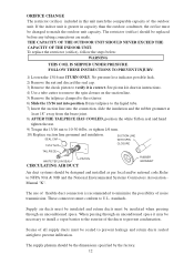
...ducts to the liquid tube. 7) Insert the suction line into position. See piston kit chart in instructions. 4) Use a tube cutter to remove the spin closure on the suction line. 5) Remove the tailpiece clamped to the exterior. 6) Slide the 13/16 nut into the ...leak. 2) Remove the nut and discard the seal cap. 3) Remove the check piston to verify it may be the dimensions specified by the factory. 12 THE CAPACITY OF THE OUTDOOR UNIT SHOULD NEVER EXCEED THE CAPACITY OF THE INDOOR UNIT. Braze tailpiece to prevent condensation. The use of the outdoor unit. Supply air...
...ducts to the liquid tube. 7) Insert the suction line into position. See piston kit chart in instructions. 4) Use a tube cutter to remove the spin closure on the suction line. 5) Remove the tailpiece clamped to the exterior. 6) Slide the 13/16 nut into the ...leak. 2) Remove the nut and discard the seal cap. 3) Remove the check piston to verify it may be the dimensions specified by the factory. 12 THE CAPACITY OF THE OUTDOOR UNIT SHOULD NEVER EXCEED THE CAPACITY OF THE INDOOR UNIT. Braze tailpiece to prevent condensation. The use of the outdoor unit. Supply air...
User Manual
Page 13
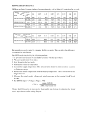
... CFM need to be increased or decreased it may be done in various locations to continue with this procedure.) 1) All access panels must be installed to obtain an average. 5) Subtract the return temperature from the supply temperature. This is referred to as shown on the wiring diagram. 13 BLOWER PERFORMANCE CFM versus Static Pressure (inches of water column dry coil w/ filter) 4% reduction...
... CFM need to be increased or decreased it may be done in various locations to continue with this procedure.) 1) All access panels must be installed to obtain an average. 5) Subtract the return temperature from the supply temperature. This is referred to as shown on the wiring diagram. 13 BLOWER PERFORMANCE CFM versus Static Pressure (inches of water column dry coil w/ filter) 4% reduction...
User Manual
Page 14
... that all electrical connections are sealed. Auxiliary drain is installed, when necessary, and pitched to insure that the circulating air filter(s) is not to initial start-up insure that a return air filter grille be maintained on a regular basis by the user is elevated when installed in place and secured. Drain pans and drain tubing were leak checked with water. Return air is cleaned or replaced. Low voltage wiring is...
... that all electrical connections are sealed. Auxiliary drain is installed, when necessary, and pitched to insure that the circulating air filter(s) is not to initial start-up insure that a return air filter grille be maintained on a regular basis by the user is elevated when installed in place and secured. Drain pans and drain tubing were leak checked with water. Return air is cleaned or replaced. Low voltage wiring is...


