User Manual
Page 2
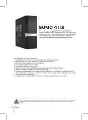
..., including power supply, hard disk, CD-ROM drive, motherboard, ventilator, etc, are not detached from the casing prior to transportation of computer products may possibly burn out the motherboard and other than its proper operation as provided in damage to your devices. Warranty void if label has been removed or tampered with the most optimal solution for purchasing a GIGABYTE Chassis. Failure...
..., including power supply, hard disk, CD-ROM drive, motherboard, ventilator, etc, are not detached from the casing prior to transportation of computer products may possibly burn out the motherboard and other than its proper operation as provided in damage to your devices. Warranty void if label has been removed or tampered with the most optimal solution for purchasing a GIGABYTE Chassis. Failure...
User Manual
Page 3
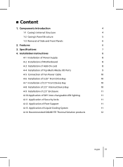
Specifications 7 4. Installation Instructions 8 4-1 Installation of Power Supply 8 4-2 Installation of Motherboard 8 4-3 Installation of Add-On card 8 4-4 Installation of Top Multi-Media I/O Ports 9 4-5 Connection of Fan Power Cable 10 4-6 Installation of 5.25" Front Drive Bay 10 4-7 Installation of 3.5" Front Device Bay 10 4-8 Installation of 3.5" Internal Device Bay 10 4-9 Installation of 2.5" Enclosure 11 4-10 Application of DIY inter-changeable LED lighting 11 4-11 Application of Security locks 11 4-12 Application of Foot Support 11 4-13 Application of Side...
Specifications 7 4. Installation Instructions 8 4-1 Installation of Power Supply 8 4-2 Installation of Motherboard 8 4-3 Installation of Add-On card 8 4-4 Installation of Top Multi-Media I/O Ports 9 4-5 Connection of Fan Power Cable 10 4-6 Installation of 5.25" Front Drive Bay 10 4-7 Installation of 3.5" Front Device Bay 10 4-8 Installation of 3.5" Internal Device Bay 10 4-9 Installation of 2.5" Enclosure 11 4-10 Application of DIY inter-changeable LED lighting 11 4-11 Application of Security locks 11 4-12 Application of Foot Support 11 4-13 Application of Side...
User Manual
Page 4
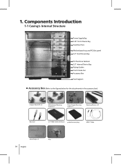
Components Introduction 1-1 Casing's Internal Structure Power Supply Bay 5.25" Front Device Bay Dual Rear fans Motherboard tray and PCI Slot panel 3.5" Front Device Bay PCI Tool-Free Fastener 3.5" Internal Device Bay Piping Outlets Front intake Fan Accessory Box Foot Support Accessory Box (Refer to the figures below for the attachments in the accessory box) Copper Stand Off x 9 Motherboard Securing Screw x 9 Power Supply Securing screw x 4 Securing Runner x10 Blue Led 2.5" HDD mobile enclosure protective carry bag USB Y Cable Wire Clamp x 2 Key 04 English 1.
Components Introduction 1-1 Casing's Internal Structure Power Supply Bay 5.25" Front Device Bay Dual Rear fans Motherboard tray and PCI Slot panel 3.5" Front Device Bay PCI Tool-Free Fastener 3.5" Internal Device Bay Piping Outlets Front intake Fan Accessory Box Foot Support Accessory Box (Refer to the figures below for the attachments in the accessory box) Copper Stand Off x 9 Motherboard Securing Screw x 9 Power Supply Securing screw x 4 Securing Runner x10 Blue Led 2.5" HDD mobile enclosure protective carry bag USB Y Cable Wire Clamp x 2 Key 04 English 1.

User Manual
Page 5
Front Cable Kit (Refer to the figures below for the cable connectors) eSATA USB 2.0 Audio (HD & AC'97) IEEE1394 (Multi-connectors) Fan 3-Pin Connector Power LED 4-pin Connector Power SW / Reset SW / HDD LED / Speaker Connector 1-2 Casing's Panel Structure a) Front Panel / Left Side Panel Red Led Disc Storage 2.5" enclosure docking Latch / Security Lock b) Top Panel Transparent side panel Ventilated mesh side panel Power Switch Multi-Media I/O port English 05
Front Cable Kit (Refer to the figures below for the cable connectors) eSATA USB 2.0 Audio (HD & AC'97) IEEE1394 (Multi-connectors) Fan 3-Pin Connector Power LED 4-pin Connector Power SW / Reset SW / HDD LED / Speaker Connector 1-2 Casing's Panel Structure a) Front Panel / Left Side Panel Red Led Disc Storage 2.5" enclosure docking Latch / Security Lock b) Top Panel Transparent side panel Ventilated mesh side panel Power Switch Multi-Media I/O port English 05
User Manual
Page 6
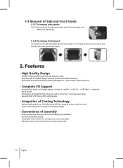
... Front Panels 1-3.1 To remove side panels: 1-3.1a. thermal solution LCS and Air cooling products lines. Integration of Cooling Technology Industry leading dual rear 12cm silent blue LED fan, Large air volume with hair-line brush anodized finishing. Supports CEB / ATX / Micro ATX motherboards. - Tool-free installation design. Features - 1-3 Removal of the side panel, and detach the side panels. 1-3.2 To remove front panel: 1-3.2a Remove the...
... Front Panels 1-3.1 To remove side panels: 1-3.1a. thermal solution LCS and Air cooling products lines. Integration of Cooling Technology Industry leading dual rear 12cm silent blue LED fan, Large air volume with hair-line brush anodized finishing. Supports CEB / ATX / Micro ATX motherboards. - Tool-free installation design. Features - 1-3 Removal of the side panel, and detach the side panels. 1-3.2 To remove front panel: 1-3.2a Remove the...

User Manual
Page 7
3. Specifications Model Case Type Dimensions Front bezel material Color Side panel Body material Net weight 5.25" drive bay (External) 3.5" drive bay (External) 3.5" drive bay (Internal) Expansion slots Form factor System Fan (front) System Fan (rear) I / O ports GZ-FAEA41-CJB FULL TOWER 205 x 522 x 500 (W x H x D) Aluminum Black Vent / Transparent SECC (0.8mm) 11.3 KG 4 1 5 7 CEB / ATX / Micro ATX 1 x 12cm silent fan 2 x 12cm blue LED illuminated silent fan 1 x eSATA / 2 x USB 2.0 / 1 x IEEE1394 / 1 x Audio Set (AC'97/HD) English 07
3. Specifications Model Case Type Dimensions Front bezel material Color Side panel Body material Net weight 5.25" drive bay (External) 3.5" drive bay (External) 3.5" drive bay (Internal) Expansion slots Form factor System Fan (front) System Fan (rear) I / O ports GZ-FAEA41-CJB FULL TOWER 205 x 522 x 500 (W x H x D) Aluminum Black Vent / Transparent SECC (0.8mm) 11.3 KG 4 1 5 7 CEB / ATX / Micro ATX 1 x 12cm silent fan 2 x 12cm blue LED illuminated silent fan 1 x eSATA / 2 x USB 2.0 / 1 x IEEE1394 / 1 x Audio Set (AC'97/HD) English 07
User Manual
Page 8
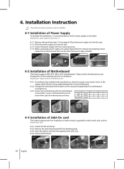
...-On card This chassis supports tool-free installation of add-on card into the case. 4-1.3 Secure the power supply with the 4 securing screws. 4-1.4 When using large power supply unit, please disassemble the cross bar by the motherboard manufacturer). 4-2.3 Secure the motherboard with care. 4-3.4 Secure the PCI clamp. 4-3.1 4-3.2 4-3.3 4-3.4 08 English 4. Required parts: power supply securing screws x 4 4-1.1 Remove side panel (see step 1-3.1on page 6). Screw in order for installation. 4-1 Installation of Power Supply To...
...-On card This chassis supports tool-free installation of add-on card into the case. 4-1.3 Secure the power supply with the 4 securing screws. 4-1.4 When using large power supply unit, please disassemble the cross bar by the motherboard manufacturer). 4-2.3 Secure the motherboard with care. 4-3.4 Secure the PCI clamp. 4-3.1 4-3.2 4-3.3 4-3.4 08 English 4. Required parts: power supply securing screws x 4 4-1.1 Remove side panel (see step 1-3.1on page 6). Screw in order for installation. 4-1 Installation of Power Supply To...
User Manual
Page 9
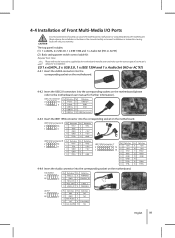
The top panel includes: (1) 1 x eSATA, 2 x USB 2.0, 1 x IEEE 1394 and 1 x Audio Set (HD or AC'97) (2) Basic casing power switch control cable kit Required Tools: None Please refer to the instructions supplied by the motherboard manufacturer and make sure the correct type of sockets can cause the motherboard to the motherboard user manual for further information). IEEE 1394 connector A Pin Definition Pin Definition 1 TPA+ 6 TPB...
The top panel includes: (1) 1 x eSATA, 2 x USB 2.0, 1 x IEEE 1394 and 1 x Audio Set (HD or AC'97) (2) Basic casing power switch control cable kit Required Tools: None Please refer to the instructions supplied by the motherboard manufacturer and make sure the correct type of sockets can cause the motherboard to the motherboard user manual for further information). IEEE 1394 connector A Pin Definition Pin Definition 1 TPA+ 6 TPB...
User Manual
Page 10
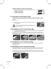
... the motherboard user manual supplied by the motherboard manufacturer. 4-6 Installation of 5.25" Front Device Bay 4-6-1 Open the front panel door and side panel, remove the plastic bezel and aluminum EMI plate through the inside of the chassis. 4-6-2 Slide-in the 5.25" device through the front panel to 5 hard disc drives (after removal of the fourth and fifth HDDs, loosen the tool enclosure, and then install the...
... the motherboard user manual supplied by the motherboard manufacturer. 4-6 Installation of 5.25" Front Device Bay 4-6-1 Open the front panel door and side panel, remove the plastic bezel and aluminum EMI plate through the inside of the chassis. 4-6-2 Slide-in the 5.25" device through the front panel to 5 hard disc drives (after removal of the fourth and fifth HDDs, loosen the tool enclosure, and then install the...

User Manual
Page 11
... or unlock. 4-12 Application of Foot Support This chassis is supplied with foot supports for ensureing the caseing is firmly secured. 4-9.4 Press the eject button and remove the 2.5"HDD mobile enclosure from the 5.25" front device housing. 4-9.1 4-9.2 4-9.3 4-9.4 4-10 Application of DIY inter changeable LED lighting 4-10-1 Remove front panel following instruction in advance. While installing the liquid cooling system, please refer to...
... or unlock. 4-12 Application of Foot Support This chassis is supplied with foot supports for ensureing the caseing is firmly secured. 4-9.4 Press the eject button and remove the 2.5"HDD mobile enclosure from the 5.25" front device housing. 4-9.1 4-9.2 4-9.3 4-9.4 4-10 Application of DIY inter changeable LED lighting 4-10-1 Remove front panel following instruction in advance. While installing the liquid cooling system, please refer to...
User Manual
Page 12
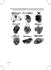
4-14 Recommended GIGABYTE Thermal Solution products The following GIGABYTE thermal solution products are recommended for use with this product. 12 English
4-14 Recommended GIGABYTE Thermal Solution products The following GIGABYTE thermal solution products are recommended for use with this product. 12 English
