User Manual
Page 7
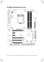
GA-Z68XP-UD4 Motherboard Layout KB_MS_USB R_SPDIF SYS_FAN1 ATX_12V_2X4 USB_1394_ESATA Marvell USB_ESATA 88SE9172 R_USB30 HDMI USB_LAN LGA1155 CPU_FAN PHASE LED PWR_FAN ATX AUDIO Etron EJ168 Realtek RTL8111E/F PCIEX16 PCIEX1_1 CODEC PCIEX1_2 PCIEX8 PCI1 VIA VT6308 PCI2 B_BIOS M_BIOS GA-Z68XP-UD4 DDR3_4 DDR3_2 DDR3_3 DDR3_1 Marvell GSATA3_7 88SE9172 GSATA3_6 SATA3_1 Intel® Z68 SATA3_0 BAT SATA2_3 SATA2_2 PCIe to PCI Bridge Etron EJ168 SATA2_5 SATA2_4 iTE IT8728 SYS_FAN2 F_AUDIO CLR_CMOS F_1394 COMA F_USB3 F_USB2 F_USB1 F_USB30 TPM F_PANEL SPDIF_O - 7 -
GA-Z68XP-UD4 Motherboard Layout KB_MS_USB R_SPDIF SYS_FAN1 ATX_12V_2X4 USB_1394_ESATA Marvell USB_ESATA 88SE9172 R_USB30 HDMI USB_LAN LGA1155 CPU_FAN PHASE LED PWR_FAN ATX AUDIO Etron EJ168 Realtek RTL8111E/F PCIEX16 PCIEX1_1 CODEC PCIEX1_2 PCIEX8 PCI1 VIA VT6308 PCI2 B_BIOS M_BIOS GA-Z68XP-UD4 DDR3_4 DDR3_2 DDR3_3 DDR3_1 Marvell GSATA3_7 88SE9172 GSATA3_6 SATA3_1 Intel® Z68 SATA3_0 BAT SATA2_3 SATA2_2 PCIe to PCI Bridge Etron EJ168 SATA2_5 SATA2_4 iTE IT8728 SYS_FAN2 F_AUDIO CLR_CMOS F_1394 COMA F_USB3 F_USB2 F_USB1 F_USB30 TPM F_PANEL SPDIF_O - 7 -
User Manual
Page 8
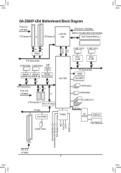
GA-Z68XP-UD4 Motherboard Block Diagram PCIe CLK (100 MHz) 1 PCI Express x16 or 2 PCI Express x8 LGA1155 CPU CPU CLK+/- (100 MHz) DDR3 2133/1866/1600/1333/1066 MHz Dual Channel ... Bus 2 SATA 6Gb/s 2 SATA 6Gb/s LAN RJ45 Marvell Marvell Realtek 88SE9172 88SE9172 RTL8111E/F x1 x1 x1 PCI Express Bus PCIe CLK (100 MHz) x1 x1 x1 Intel® Z68 2 PCI Express x1 PCIe to PCI Bridge PCI Bus VIA VT6308 CODEC 2 IEEE 1394a DMI 2.0 FDI 2 USB 3.0/2.0 2 USB 3.0/2.0 Etron EJ168 Etron EJ168 x1...
GA-Z68XP-UD4 Motherboard Block Diagram PCIe CLK (100 MHz) 1 PCI Express x16 or 2 PCI Express x8 LGA1155 CPU CPU CLK+/- (100 MHz) DDR3 2133/1866/1600/1333/1066 MHz Dual Channel ... Bus 2 SATA 6Gb/s 2 SATA 6Gb/s LAN RJ45 Marvell Marvell Realtek 88SE9172 88SE9172 RTL8111E/F x1 x1 x1 PCI Express Bus PCIe CLK (100 MHz) x1 x1 x1 Intel® Z68 2 PCI Express x1 PCIe to PCI Bridge PCI Bus VIA VT6308 CODEC 2 IEEE 1394a DMI 2.0 FDI 2 USB 3.0/2.0 2 USB 3.0/2.0 Etron EJ168 Etron EJ168 x1...

User Manual
Page 29
.... Each USB header can provide two USB ports via an UG T optional USB bracket. For purchasing the optional USB bracket, please contact the local dealer. PCIe power connector (SATA)(X58A-OC) Hardware Installation Pin No. TPM Voltage measurement module(X58A-OC) •• Do not plug the IEEE 1394 bracketw(/h2oxu5si...
.... Each USB header can provide two USB ports via an UG T optional USB bracket. For purchasing the optional USB bracket, please contact the local dealer. PCIe power connector (SATA)(X58A-OC) Hardware Installation Pin No. TPM Voltage measurement module(X58A-OC) •• Do not plug the IEEE 1394 bracketw(/h2oxu5si...

User Manual
Page 31
... No Pin LRESET NC LAD3 LAD2 VCC3 LAD1 1 Voltage measurement module(X58A-OC) PWM Swi DIP 2 DIP Pin No. Definition 1 23 11 LAD0 12 GND PCIe power connector (SATA)(X58A-OC) 13 NC 14 ID 15 SB3V 16 SERIRQ 17 GND 18 NC 19 NC 20 SUSCLK - 31 - 18) PHASE LED...
... No Pin LRESET NC LAD3 LAD2 VCC3 LAD1 1 Voltage measurement module(X58A-OC) PWM Swi DIP 2 DIP Pin No. Definition 1 23 11 LAD0 12 GND PCIe power connector (SATA)(X58A-OC) 13 NC 14 ID 15 SB3V 16 SERIRQ 17 GND 18 NC 19 NC 20 SUSCLK - 31 - 18) PHASE LED...

User Manual
Page 40
...below to emit PROCHOT signals. >>>>> Standard Clock Control BCLK/DMI/PEG Clock Control Enables or disables the control of CPU base clock and DMI/PCIe bus frequency. Important: It is present only if you install a CPU that the CPU frequency be set in system halt state. C3/C6 ...State Support (Note 1) Allows you to manually set the CPU base clock and DMI/PCIe bus frequency. Auto sets memory multiplier according to memory SPD data. (Default: Auto) (Note 1) This item is highly recommended that supports this feature...
...below to emit PROCHOT signals. >>>>> Standard Clock Control BCLK/DMI/PEG Clock Control Enables or disables the control of CPU base clock and DMI/PCIe bus frequency. Important: It is present only if you install a CPU that the CPU frequency be set in system halt state. C3/C6 ...State Support (Note 1) Allows you to manually set the CPU base clock and DMI/PCIe bus frequency. Auto sets memory multiplier according to memory SPD data. (Default: Auto) (Note 1) This item is highly recommended that supports this feature...

User Manual
Page 49
... read/write errors of your system to initialize the hard drive as the first display. Onboard VGA Enables or disables the onboard graphics function. PCIE x8 Sets the PCI Express graphics card on the PCIEX16 slot as the system boots up a dual-display configuration, set up a dual-display... system memory allocated solely for example, will use only this item to display the GIGABYTE Logo at system startup. PCI Sets the PCI graphics card on the PCI slot as the first display. (Default) PCIE x16 Sets the PCI Express graphics card on the PCIEX8 slot as the first display...
... read/write errors of your system to initialize the hard drive as the first display. Onboard VGA Enables or disables the onboard graphics function. PCIE x8 Sets the PCI Express graphics card on the PCIEX16 slot as the system boots up a dual-display configuration, set up a dual-display... system memory allocated solely for example, will use only this item to display the GIGABYTE Logo at system startup. PCI Sets the PCI graphics card on the PCI slot as the first display. (Default) PCIE x16 Sets the PCI Express graphics card on the PCIEX8 slot as the first display...

User Manual
Page 53
... mode. PME Event Wake Up Allows the system to be turned off instantly. (Default) Delay 4 Sec. Soft-Off by a wake-up signal from a PCI or PCIe device. Press and hold the power button for less than in the S1 state. If the power button is pressed for 4 seconds to turn off...
... mode. PME Event Wake Up Allows the system to be turned off instantly. (Default) Delay 4 Sec. Soft-Off by a wake-up signal from a PCI or PCIe device. Press and hold the power button for less than in the S1 state. If the power button is pressed for 4 seconds to turn off...
User Manual
Page 82
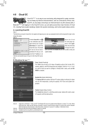
... which will provide a word, and then click Send and you can easily access three major functions of tweaking options that include CPU, memory, graphics, and PCIe frequencies and voltages. Step 2: Step 3: Find the Cloud OC icon When the Cloud in power off , suspend, and hibernate options. (Note 1) (Note 2) (Note 3) Supported on...
... which will provide a word, and then click Send and you can easily access three major functions of tweaking options that include CPU, memory, graphics, and PCIe frequencies and voltages. Step 2: Step 3: Find the Cloud OC icon When the Cloud in power off , suspend, and hibernate options. (Note 1) (Note 2) (Note 3) Supported on...

User Manual
Page 94
... key to continue" (Figure 2). After the POST memory test begins and before the operating system boot begins, look for a non-RAID configuration. BIOS Version 1.0.0.0017 PCIe x2 5.0Gbps Mode: RAID [Virtual Disks] No Virtual Disk! [Physical Disks] Adapter 0 Port Disk Name S0 SATA: WDC WD800JD-22LSA0 S1 SATA: WDC WD800JD-22LSA0...
... key to continue" (Figure 2). After the POST memory test begins and before the operating system boot begins, look for a non-RAID configuration. BIOS Version 1.0.0.0017 PCIe x2 5.0Gbps Mode: RAID [Virtual Disks] No Virtual Disk! [Physical Disks] Adapter 0 Port Disk Name S0 SATA: WDC WD800JD-22LSA0 S1 SATA: WDC WD800JD-22LSA0...


