Manual
Page 3
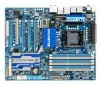
... product. For instructions on our website. Check your motherboard looks like this manual are legally registered to the specifications and features in this : "REV: X.X." All rights reserved. The trademarks mentioned in this product, GIGABYTE provides the following types of documentations: For quick set-up of the motherboard is the property of this...
... product. For instructions on our website. Check your motherboard looks like this manual are legally registered to the specifications and features in this : "REV: X.X." All rights reserved. The trademarks mentioned in this product, GIGABYTE provides the following types of documentations: For quick set-up of the motherboard is the property of this...
Manual
Page 4
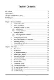
Table of Contents Box Contents...6 Optional Items...6 GA-X58A-UD5 Motherboard Layout 7 Block Diagram...8 Chapter 1 Hardware Installation 9 1-1 Installation Precautions 9 1-2 Product Specifications 10 1-3 Installing the CPU and CPU Cooler 13 1-3-1 Installing the CPU 13 1-3-2 Installing the CPU Cooler 15 1-4 Installing the Memory 16 1-4-1 Dual/3 Channel Memory Configuration ...
Table of Contents Box Contents...6 Optional Items...6 GA-X58A-UD5 Motherboard Layout 7 Block Diagram...8 Chapter 1 Hardware Installation 9 1-1 Installation Precautions 9 1-2 Product Specifications 10 1-3 Installing the CPU and CPU Cooler 13 1-3-1 Installing the CPU 13 1-3-2 Installing the CPU Cooler 15 1-4 Installing the Memory 16 1-4-1 Dual/3 Channel Memory Configuration ...
Manual
Page 10
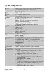
1-2 Product Specifications CPU Support for an Intel® Core™ i7 series processor in the LGA1366 package (Go to GIGABYTE's website for the latest CPU support list.) L3 cache varies with CPU QPI 4.8GT/s, 6.4GT/s ...SATA 3Gb/s connectors (SATA2_0, SATA2_1, SATA2_2, SATA2_3, SATA2_4, SATA2_5) supporting up to 2 SATA 3Gb/s devices - Support for SATA RAID 0, and RAID 1 GIGABYTE SATA2 chip: - 1 x IDE connector supporting ATA-133/100/66/33 and up to 2 IDE devices - 2 x SATA 3Gb/s connectors (GSATA2_8, GSATA2_9) supporting up...
1-2 Product Specifications CPU Support for an Intel® Core™ i7 series processor in the LGA1366 package (Go to GIGABYTE's website for the latest CPU support list.) L3 cache varies with CPU QPI 4.8GT/s, 6.4GT/s ...SATA 3Gb/s connectors (SATA2_0, SATA2_1, SATA2_2, SATA2_3, SATA2_4, SATA2_5) supporting up to 2 SATA 3Gb/s devices - Support for SATA RAID 0, and RAID 1 GIGABYTE SATA2 chip: - 1 x IDE connector supporting ATA-133/100/66/33 and up to 2 IDE devices - 2 x SATA 3Gb/s connectors (GSATA2_8, GSATA2_9) supporting up...
Manual
Page 13
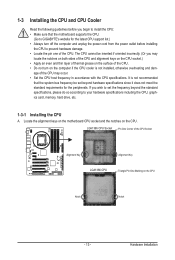
... the CPU: • Make sure that the motherboard supports the CPU. (Go to GIGABYTE's website for the peripherals. If you may occur. • Set the CPU host frequency in accordance with the CPU specifications. LGA1366 CPU Socket Pin One Corner of the CPU. Locate the alignment keys on the... the CPU cooler is not recommended that the system bus frequency be inserted if oriented incorrectly. (Or you wish to set beyond the standard specifications, please do so according to prevent hardware damage. • Locate the pin one of the CPU Socket Alignment Key Alignment Key LGA1366 CPU...
... the CPU: • Make sure that the motherboard supports the CPU. (Go to GIGABYTE's website for the peripherals. If you may occur. • Set the CPU host frequency in accordance with the CPU specifications. LGA1366 CPU Socket Pin One Corner of the CPU. Locate the alignment keys on the... the CPU cooler is not recommended that the system bus frequency be inserted if oriented incorrectly. (Or you wish to set beyond the standard specifications, please do so according to prevent hardware damage. • Locate the pin one of the CPU Socket Alignment Key Alignment Key LGA1366 CPU...
Manual
Page 16
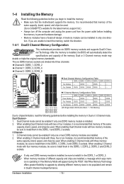
.... DS/SS Four Modules DS/SS DS/SS - - When enabling 3 Channel mode with three memory modules, be used. (Go to GIGABYTE's website for the latest memory support list.) • Always turn off the computer and unplug the power cord from the power outlet before ...DDR3_1, DDR3_2, DDR3_3 and DDR3_5 sockets. • If only one DDR3 memory module is operating in Flex Memory Mode will automatically detect the specifications and capacity of different capacity and chips are divided into three channels: Channel 0: DDR3_1, DDR3_2 Channel 1: DDR3_3, DDR3_4 Channel 2: DDR3_5, DDR3_6...
.... DS/SS Four Modules DS/SS DS/SS - - When enabling 3 Channel mode with three memory modules, be used. (Go to GIGABYTE's website for the latest memory support list.) • Always turn off the computer and unplug the power cord from the power outlet before ...DDR3_1, DDR3_2, DDR3_3 and DDR3_5 sockets. • If only one DDR3 memory module is operating in Flex Memory Mode will automatically detect the specifications and capacity of different capacity and chips are divided into three channels: Channel 0: DDR3_1, DDR3_2 Channel 1: DDR3_3, DDR3_4 Channel 2: DDR3_5, DDR3_6...

Manual
Page 20
...such as a USB keyboard/mouse, USB printer, USB flash drive and etc. IEEE 1394a Port The IEEE 1394 port supports the IEEE 1394a specification, featuring high speed, high bandwidth and hotplug capabilities. scribes the states of the LAN port LEDs. Use this port for an IEEE 1394a... device. The following de- Use the port to connect a PS/2 keyboard. eSATA/USB Combo Connector This connector supports SATA 3Gb/s and USB 2.0/1.1 specification. 1-7 Back Panel Connectors clr CMOS PS/2 Keyboard and PS/2 Mouse Port Use the upper port (green) to connect a PS/2 mouse and the lower...
...such as a USB keyboard/mouse, USB printer, USB flash drive and etc. IEEE 1394a Port The IEEE 1394 port supports the IEEE 1394a specification, featuring high speed, high bandwidth and hotplug capabilities. scribes the states of the LAN port LEDs. Use this port for an IEEE 1394a... device. The following de- Use the port to connect a PS/2 keyboard. eSATA/USB Combo Connector This connector supports SATA 3Gb/s and USB 2.0/1.1 specification. 1-7 Back Panel Connectors clr CMOS PS/2 Keyboard and PS/2 Mouse Port Use the upper port (green) to connect a PS/2 mouse and the lower...
Manual
Page 21
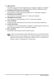
... in a 7.1-channel audio configuration. This jack can be used to connect rear speakers in a 4/5.1/7.1-channel audio configuration. USB 3.0/2.0 Port The USB 3.0 port supports the USB 3.0 specification and is compatible to this jack. Line Out Jack (Green) The default line out jack. Use this audio jack to the instructions on setting up... Chapter 5, "Configuring 2/4/5.1/7.1-Channel Audio." - 21 - Line In Jack (Blue) The default line in a 5.1/7.1-channel audio configuration. Only microphones still MUST be connected to the USB 2.0/1.1 specification.
... in a 7.1-channel audio configuration. This jack can be used to connect rear speakers in a 4/5.1/7.1-channel audio configuration. USB 3.0/2.0 Port The USB 3.0 port supports the USB 3.0 specification and is compatible to this jack. Line Out Jack (Green) The default line out jack. Use this audio jack to the instructions on setting up... Chapter 5, "Configuring 2/4/5.1/7.1-Channel Audio." - 21 - Line In Jack (Blue) The default line in a 5.1/7.1-channel audio configuration. Only microphones still MUST be connected to the USB 2.0/1.1 specification.

Manual
Page 34
... USB header can provide one end of the device cable to your computer and then attach the other end of the cable to IEEE 1394a specification. Definition 1 TPA+ 9 1 2 TPA- 10 2 3 GND 4 GND 5 TPB+ 6 TPB- 7 Power (12V) 8 Power (12V) 9 No Pin 10 GND • Do not plug the USB bracket cable into... installing the USB bracket, be sure to turn off your computer and unplug the power cord from the power outlet to prevent damage to USB 2.0/1.1 specification.
... USB header can provide one end of the device cable to your computer and then attach the other end of the cable to IEEE 1394a specification. Definition 1 TPA+ 9 1 2 TPA- 10 2 3 GND 4 GND 5 TPB+ 6 TPB- 7 Power (12V) 8 Power (12V) 9 No Pin 10 GND • Do not plug the USB bracket cable into... installing the USB bracket, be sure to turn off your computer and unplug the power cord from the power outlet to prevent damage to USB 2.0/1.1 specification.
Manual
Page 44
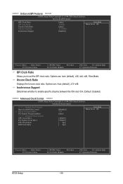
... Values +/-/PU/PD: Value F10: Save F6: Fail-Safe Defaults ESC: Exit F1: General Help F7: Optimized Defaults QPI Clock Ratio Allows you to enable specific streams between the IOH and ICH. (Default: Enabled) ******** Advanced Clock Control ******** CMOS Setup Utility-Copyright (C) 1984-2009 Award Software Advanced Clock Control >>>>> Sandard Clock Control...
... Values +/-/PU/PD: Value F10: Save F6: Fail-Safe Defaults ESC: Exit F1: General Help F7: Optimized Defaults QPI Clock Ratio Allows you to enable specific streams between the IOH and ICH. (Default: Enabled) ******** Advanced Clock Control ******** CMOS Setup Utility-Copyright (C) 1984-2009 Award Software Advanced Clock Control >>>>> Sandard Clock Control...
Manual
Page 45
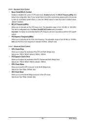
... clear the CMOS values to reset the board to default values. (Default: Disabled) BCLK Frequency(Mhz) Allows you to set in accordance with the CPU specifications. PCI Express Frequency(Mhz) Allows you to adjust the amplitude of CPU base clock. Important: It is enabled.
... clear the CMOS values to reset the board to default values. (Default: Disabled) BCLK Frequency(Mhz) Allows you to set in accordance with the CPU specifications. PCI Express Frequency(Mhz) Allows you to adjust the amplitude of CPU base clock. Important: It is enabled.

Manual
Page 50
Enabling Load-Line Calibration may result in damage to adjust Vdroop at different levels. Standard Disables Load-Line Calibration and sets VDroop following Intel specifications. (De- QPI/Vtt Voltage The default is Auto. CPU PLL The default is Auto. >>>>> MCH/ICH PCIE The default is Auto. Ch-B Data VRef. The ...
Enabling Load-Line Calibration may result in damage to adjust Vdroop at different levels. Standard Disables Load-Line Calibration and sets VDroop following Intel specifications. (De- QPI/Vtt Voltage The default is Auto. CPU PLL The default is Auto. >>>>> MCH/ICH PCIE The default is Auto. Ch-B Data VRef. The ...

Manual
Page 52
... 360K/5.25", 1.2M/5.25", 720K/3.5", 1.44M/3.5", 2.88M/3.5". Options are: Auto (default), CHS, LBA, Large. Extended IDE Drive Configure your hard drive specifications. Drive A Allows you to the information on the system. • Auto Lets the BIOS automatically detect IDE/SATA devices during the POST. (Default) •... of the device during the POST for faster system startup. • Manual Allows you to manually enter the specifications of the hard drive when the hard drive access mode is set to CHS. Cylinder Number of cylinders. Landing Zone Landing zone...
... 360K/5.25", 1.2M/5.25", 720K/3.5", 1.44M/3.5", 2.88M/3.5". Options are: Auto (default), CHS, LBA, Large. Extended IDE Drive Configure your hard drive specifications. Drive A Allows you to the information on the system. • Auto Lets the BIOS automatically detect IDE/SATA devices during the POST. (Default) •... of the device during the POST for faster system startup. • Manual Allows you to manually enter the specifications of the hard drive when the hard drive access mode is set to CHS. Cylinder Number of cylinders. Landing Zone Landing zone...

Manual
Page 56
... SATA controllers to Disabled. USB 1.0 Controller Enables or disables the integrated USB 1.0 controller. (Default: Enabled) Disabled will dynamically detect if a LAN cable is an interface specification that support Native mode. Green LAN When the onboard LAN function and Green LAN are enabled, the system will turn off all of using the...
... SATA controllers to Disabled. USB 1.0 Controller Enables or disables the integrated USB 1.0 controller. (Default: Enabled) Disabled will dynamically detect if a LAN cable is an interface specification that support Native mode. Green LAN When the onboard LAN function and Green LAN are enabled, the system will turn off all of using the...
Manual
Page 58
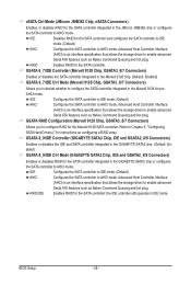
... controller to AHCI mode. RAID Enables RAID for the SATA controller; Advanced Host Controller Interface (AHCI) is an interface specification that allows the storage driver to enable advanced Serial ATA features such as Native Command Queuing and hot plug. IDE Configures... integrated in the GIGABYTE SATA2 chip. (Default: Enabled) GSATA 8_9/IDE Ctrl Mode (GIGABYTE SATA2 Chip, IDE and GSATA2_8/9 Connectors) Enables or disables RAID for instructions on configuring a RAID array. Advanced Host Controller Interface (AHCI) is an interface specification that allows the ...
... controller to AHCI mode. RAID Enables RAID for the SATA controller; Advanced Host Controller Interface (AHCI) is an interface specification that allows the storage driver to enable advanced Serial ATA features such as Native Command Queuing and hot plug. IDE Configures... integrated in the GIGABYTE SATA2 chip. (Default: Enabled) GSATA 8_9/IDE Ctrl Mode (GIGABYTE SATA2 Chip, IDE and GSATA2_8/9 Connectors) Enables or disables RAID for instructions on configuring a RAID array. Advanced Host Controller Interface (AHCI) is an interface specification that allows the ...

Manual
Page 60
... system. BIOS Setup - 60 - Resume by Alarm Determines whether to Enabled, the following : Date (of Month) Alarm: Turn on the system at a specific time on each day or on a specific day in S5 (shutdown) state. (Default: Disabled) Note: When this function, you need an ATX power supply providing at least 1A on...
... system. BIOS Setup - 60 - Resume by Alarm Determines whether to Enabled, the following : Date (of Month) Alarm: Turn on the system at a specific time on each day or on a specific day in S5 (shutdown) state. (Default: Disabled) Note: When this function, you need an ATX power supply providing at least 1A on...

Manual
Page 62
CPU Smart FAN Mode Specifies how to Enabled. This item is configurable only if CPU Smart FAN Control is not designed following Intel PWM fan specifications, selecting PWM mode may not effectively reduce the fan speed. Note: The Voltage mode can be set to control CPU fan speed. BIOS Setup - 62 - ...
CPU Smart FAN Mode Specifies how to Enabled. This item is configurable only if CPU Smart FAN Control is not designed following Intel PWM fan specifications, selecting PWM mode may not effectively reduce the fan speed. Note: The Voltage mode can be set to control CPU fan speed. BIOS Setup - 62 - ...
Manual
Page 78
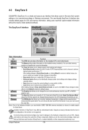
...(s). The Graphics tab allows you to enable support for these changes to take effect or click Default to restore to be changed linearly based on a specific slot to the hardware components such as CPU, chipset, and memory and reduce the useful life of these changes to take effect. • Easy mode... you fully know each function of CPU frequency/base clock to choose to achieve desired system performance. (Note) After making changes in Windows environment. 4-3 EasyTune 6 GIGABYTE's EasyTune 6 is not supported.
...(s). The Graphics tab allows you to enable support for these changes to take effect or click Default to restore to be changed linearly based on a specific slot to the hardware components such as CPU, chipset, and memory and reduce the useful life of these changes to take effect. • Easy mode... you fully know each function of CPU frequency/base clock to choose to achieve desired system performance. (Note) After making changes in Windows environment. 4-3 EasyTune 6 GIGABYTE's EasyTune 6 is not supported.

Manual
Page 83
... Schedule Capacity Function Enables automatic daily backup (Note 3) Sets a daily backup schedule Sets the percentage of hard drive space used for copying files/folders from a specific backup on PATA and SATA hard drives (partitioned on the right or at different time, select a backup time using the time bar on NTFS file...
... Schedule Capacity Function Enables automatic daily backup (Note 3) Sets a daily backup schedule Sets the percentage of hard drive space used for copying files/folders from a specific backup on PATA and SATA hard drives (partitioned on the right or at different time, select a backup time using the time bar on NTFS file...

Manual
Page 87
... Ethernet Diagnostic Utility for the two available adapters and click OK. Step 2: Click the Start icon . Select the check boxes for installation. Restart your hub's specifications. Step 4: Give a name for further details. Go to access the utility. Removing the Existing Teaming: Step 5: After you complete the setup, you will see the...
... Ethernet Diagnostic Utility for the two available adapters and click OK. Step 2: Click the Start icon . Select the check boxes for installation. Restart your hub's specifications. Step 4: Give a name for further details. Go to access the utility. Removing the Existing Teaming: Step 5: After you complete the setup, you will see the...