
Manual
Page 1
...helps to enhance your needs and hardware components. 3. You can go to the Application Software screen to individually install the X.H.D utility later. Using GIGABYTE eXtreme Hard Drive (X.H.D) Instructions:(Note 2) Before launching X.H.D, make sure the new drive is greater than the RAID-ready system drive. (To add...on your hard drive read/write performance without the need for RAID 0 when a new SATA drive is added. eXtreme Hard Drive (X.H.D) With GIGABYTE eXtreme Hard Drive (X.H.D)(Note 1), users can use X.H.D to easily add a hard drive into a RAID 0 array that's been created earlier,...
...helps to enhance your needs and hardware components. 3. You can go to the Application Software screen to individually install the X.H.D utility later. Using GIGABYTE eXtreme Hard Drive (X.H.D) Instructions:(Note 2) Before launching X.H.D, make sure the new drive is greater than the RAID-ready system drive. (To add...on your hard drive read/write performance without the need for RAID 0 when a new SATA drive is added. eXtreme Hard Drive (X.H.D) With GIGABYTE eXtreme Hard Drive (X.H.D)(Note 1), users can use X.H.D to easily add a hard drive into a RAID 0 array that's been created earlier,...
Manual
Page 1
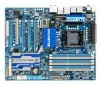
GA-X58A-UD5 LGA1366 socket motherboard for Intel® Core™ i7 processor family User's Manual Rev. 1001 12ME-X58AUD5-1001R
GA-X58A-UD5 LGA1366 socket motherboard for Intel® Core™ i7 processor family User's Manual Rev. 1001 12ME-X58AUD5-1001R
Manual
Page 2
Motherboard GA-X58A-UD5 Dec. 25, 2009 Motherboard GA-X58A-UD5 Dec. 25, 2009
Motherboard GA-X58A-UD5 Dec. 25, 2009 Motherboard GA-X58A-UD5 Dec. 25, 2009
Manual
Page 3
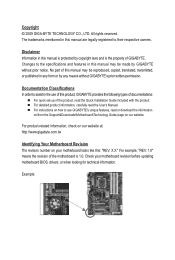
...Quick Installation Guide included with the product. Changes to their respective owners. No part of the motherboard is protected by GIGABYTE without GIGABYTE's prior written permission. For example, "REV: 1.0" means the revision of this manual are legally registered to the specifications and..., drivers, or when looking for technical information. Example: For product-related information, check on our website at: http://www.gigabyte.com.tw Identifying Your Motherboard Revision The revision number on our website. Documentation Classifications In order to use of the product, ...
...Quick Installation Guide included with the product. Changes to their respective owners. No part of the motherboard is protected by GIGABYTE without GIGABYTE's prior written permission. For example, "REV: 1.0" means the revision of this manual are legally registered to the specifications and..., drivers, or when looking for technical information. Example: For product-related information, check on our website at: http://www.gigabyte.com.tw Identifying Your Motherboard Revision The revision number on our website. Documentation Classifications In order to use of the product, ...
Manual
Page 4
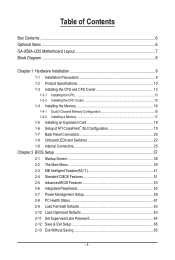
Table of Contents Box Contents...6 Optional Items...6 GA-X58A-UD5 Motherboard Layout 7 Block Diagram...8 Chapter 1 Hardware Installation 9 1-1 Installation Precautions 9 1-2 Product Specifications 10 1-3 Installing the CPU and CPU Cooler 13 1-3-1 Installing the CPU 13 1-3-2 Installing the ...
Table of Contents Box Contents...6 Optional Items...6 GA-X58A-UD5 Motherboard Layout 7 Block Diagram...8 Chapter 1 Hardware Installation 9 1-1 Installation Precautions 9 1-2 Product Specifications 10 1-3 Installing the CPU and CPU Cooler 13 1-3-1 Installing the CPU 13 1-3-2 Installing the ...
Manual
Page 5
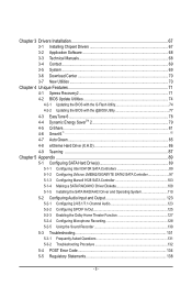
... Green...85 4-8 eXtreme Hard Drive (X.H.D 86 4-9 Teaming 87 Chapter 5 Appendix...89 5-1 Configuring SATA Hard Drive(s 89 5-1-1 Configuring Intel ICH10R SATA Controllers 89 5-1-2 Configuring JMicron JMB362/GIGABYTE SATA2 SATA Controller 97 5-1-3 Configuring Marvell 9128 SATA Controller 103 5-1-4 Making a SATA RAID/AHCI Driver Diskette 108 5-1-5 Installing the SATA RAID/AHCI Driver and Operating...
... Green...85 4-8 eXtreme Hard Drive (X.H.D 86 4-9 Teaming 87 Chapter 5 Appendix...89 5-1 Configuring SATA Hard Drive(s 89 5-1-1 Configuring Intel ICH10R SATA Controllers 89 5-1-2 Configuring JMicron JMB362/GIGABYTE SATA2 SATA Controller 97 5-1-3 Configuring Marvell 9128 SATA Controller 103 5-1-4 Making a SATA RAID/AHCI Driver Diskette 108 5-1-5 Installing the SATA RAID/AHCI Driver and Operating...
Manual
Page 6
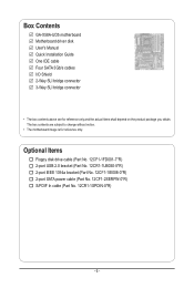
...-5*R) 2-port IEEE 1394a bracket (Part No. 12CF1-1IE008-0*R) 2-port SATA power cable (Part No. 12CF1-2SERPW-0*R) S/PDIF In cable (Part No. 12CR1-1SPDIN-0*R) - 6 - Box Contents GA-X58A-UD5 motherboard Motherboard driver disk User's Manual Quick Installation Guide One IDE cable Four SATA 3Gb/s cables I/O Shield 2-Way SLI bridge connector 3-Way SLI bridge connector...
...-5*R) 2-port IEEE 1394a bracket (Part No. 12CF1-1IE008-0*R) 2-port SATA power cable (Part No. 12CF1-2SERPW-0*R) S/PDIF In cable (Part No. 12CR1-1SPDIN-0*R) - 6 - Box Contents GA-X58A-UD5 motherboard Motherboard driver disk User's Manual Quick Installation Guide One IDE cable Four SATA 3Gb/s cables I/O Shield 2-Way SLI bridge connector 3-Way SLI bridge connector...
Manual
Page 7
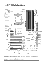
... expansion card. LED PHASE LED KB_MS R_SPDIF ATX_12V_2X CMOS_SW USB_1394_ESATA_2 USB_1394_ESATA_1 CPU_FAN CPU Voltage L1/2/3 CPU TEMP L1/2 LGA1366 RST_SW PW_SW GA-X58A-UD5 PWR_FAN USB_LAN ATX USB30_LAN JMicron JMB362 DDR Voltage LED DDR PHASE LED F_AUDIO NB TEMP L1/2 AUDIO NEC PCIEX1_1(Note 1) RTL8111D ...L1/2/3 BAT Intel® ICH10R Marvell 9128 SATA2_1 SATA2_0 SATA2_3 SATA2_2 SATA2_5 SATA2_4 GSATA3_7 GSATA3_6 SYS_FAN3 TSB43AB23 GIGABYTE SATA2 Debug LED (Note 2) GSATA2_9 GSATA2_8 SYS_FAN2 F_USB2 IDE F_PANEL FDD F_1394 F_USB1 (Note 1) Due to Chapter 5. - 7 -
... expansion card. LED PHASE LED KB_MS R_SPDIF ATX_12V_2X CMOS_SW USB_1394_ESATA_2 USB_1394_ESATA_1 CPU_FAN CPU Voltage L1/2/3 CPU TEMP L1/2 LGA1366 RST_SW PW_SW GA-X58A-UD5 PWR_FAN USB_LAN ATX USB30_LAN JMicron JMB362 DDR Voltage LED DDR PHASE LED F_AUDIO NB TEMP L1/2 AUDIO NEC PCIEX1_1(Note 1) RTL8111D ...L1/2/3 BAT Intel® ICH10R Marvell 9128 SATA2_1 SATA2_0 SATA2_3 SATA2_2 SATA2_5 SATA2_4 GSATA3_7 GSATA3_6 SYS_FAN3 TSB43AB23 GIGABYTE SATA2 Debug LED (Note 2) GSATA2_9 GSATA2_8 SYS_FAN2 F_USB2 IDE F_PANEL FDD F_1394 F_USB1 (Note 1) Due to Chapter 5. - 7 -
Manual
Page 8
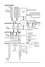
... x1 x1 x1 (100 MHz) JMicron JMB362 Intel® ICH10R 2 PCI Express x1 x1 2 eSATA 3Gb/s 2 SATA 3Gb/s ATA-133/100/66/33 IDE Channel GIGABYTE SATA2 PCI Bus TSB43AB23 CODEC Dual BIOS 6 SATA 3Gb/s 10 USB 2.0/1.1 LPC Bus IT8720 Floppy PS/2 KB/Mouse 3 IEEE 1394a Surround Speaker Out Center/Subwoofer...
... x1 x1 x1 (100 MHz) JMicron JMB362 Intel® ICH10R 2 PCI Express x1 x1 2 eSATA 3Gb/s 2 SATA 3Gb/s ATA-133/100/66/33 IDE Channel GIGABYTE SATA2 PCI Bus TSB43AB23 CODEC Dual BIOS 6 SATA 3Gb/s 10 USB 2.0/1.1 LPC Bus IT8720 Floppy PS/2 KB/Mouse 3 IEEE 1394a Surround Speaker Out Center/Subwoofer...
Manual
Page 9
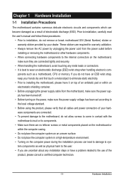
If you are no leftover screws or metal components placed on the motherboard or within an electrostatic shielding container. • Before unplugging the power supply cable from the motherboard, make sure the power supply has been turned off. • Before turning on the power, make sure they are connected tightly and securely. • When handling the motherboard, avoid touching any installation steps or have it on top of an antistatic pad or within the computer casing. • Do not place the computer system on an uneven surface. • Do not place the computer system in ...
If you are no leftover screws or metal components placed on the motherboard or within an electrostatic shielding container. • Before unplugging the power supply cable from the motherboard, make sure the power supply has been turned off. • Before turning on the power, make sure they are connected tightly and securely. • When handling the motherboard, avoid touching any installation steps or have it on top of an antistatic pad or within the computer casing. • Do not place the computer system on an uneven surface. • Do not place the computer system in ...
Manual
Page 10
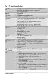
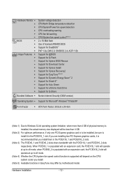
... devices - 1-2 Product Specifications CPU Support for an Intel® Core™ i7 series processor in the LGA1366 package (Go to GIGABYTE's website for the latest CPU support list.) L3 cache varies with CPU QPI 4.8GT/s, 6.4GT/s Chipset North...modules Support for non-ECC memory modules Support for Extreme Memory Profile (XMP) memory modules Audio (Go to GIGABYTE's website for the latest memory support list.) Realtek ALC889 codec High Definition Audio 2/4/5.1/7.1-channel ...
... devices - 1-2 Product Specifications CPU Support for an Intel® Core™ i7 series processor in the LGA1366 package (Go to GIGABYTE's website for the latest CPU support list.) L3 cache varies with CPU QPI 4.8GT/s, 6.4GT/s Chipset North...modules Support for non-ECC memory modules Support for Extreme Memory Profile (XMP) memory modules Audio (Go to GIGABYTE's website for the latest memory support list.) Realtek ALC889 codec High Definition Audio 2/4/5.1/7.1-channel ...
Manual
Page 11
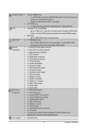
TSB43AB23 chip - Up to 2 USB 3.0/2.0 ports on the back panel, 1 via the USB brackets connected to the internal USB headers) NEC chip: - Up to 3 IEEE 1394a ports (2 on the back panel IEEE 1394 T.I /O Controller w iTE IT8720 chip - 11 - Hardware Installation Support for SATA RAID 0, RAID 1, and JBOD iTE IT8720 chip: - 1 x floppy disk drive connector supporting up to 2 SATA 3Gb/s devices - Storage Interface JMicron JMB362 chip: - 2 x eSATA 3Gb/s connectors (eSATA/USB Combo) on the back panel, including 2...
TSB43AB23 chip - Up to 2 USB 3.0/2.0 ports on the back panel, 1 via the USB brackets connected to the internal USB headers) NEC chip: - Up to 3 IEEE 1394a ports (2 on the back panel IEEE 1394 T.I /O Controller w iTE IT8720 chip - 11 - Hardware Installation Support for SATA RAID 0, RAID 1, and JBOD iTE IT8720 chip: - 1 x floppy disk drive connector supporting up to 2 SATA 3Gb/s devices - Storage Interface JMicron JMB362 chip: - 2 x eSATA 3Gb/s connectors (eSATA/USB Combo) on the back panel, including 2...
Manual
Page 12
When PCIEX8_1 is populated with the PCIEX16_1 and PCIEX16_2 slots respectively. Hardware Installation - 12 - if you are installing two PCI Express graphics cards, it in the PCIEX16_1 slot; Hardware Monitor w w w w w w BIOS w w w w Unique Features w w w w w w w w w w w w Bundled Software w System voltage detection CPU/North Bridge temperature detection CPU/System/Power fan speed detection CPU overheating warning CPU fan fail warning CPU/System fan speed control (...
When PCIEX8_1 is populated with the PCIEX16_1 and PCIEX16_2 slots respectively. Hardware Installation - 12 - if you are installing two PCI Express graphics cards, it in the PCIEX16_1 slot; Hardware Monitor w w w w w w BIOS w w w w Unique Features w w w w w w w w w w w w Bundled Software w System voltage detection CPU/North Bridge temperature detection CPU/System/Power fan speed detection CPU overheating warning CPU fan fail warning CPU/System fan speed control (...
Manual
Page 13
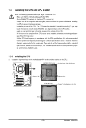
... the power cord from the power outlet before you begin to install the CPU: • Make sure that the motherboard supports the CPU. (Go to GIGABYTE's website for the peripherals. age of the CPU Socket Alignment Key Alignment Key LGA1366 CPU Triangle Pin One Marking on the CPU. Locate the alignment...
... the power cord from the power outlet before you begin to install the CPU: • Make sure that the motherboard supports the CPU. (Go to GIGABYTE's website for the peripherals. age of the CPU Socket Alignment Key Alignment Key LGA1366 CPU Triangle Pin One Marking on the CPU. Locate the alignment...
Manual
Page 14
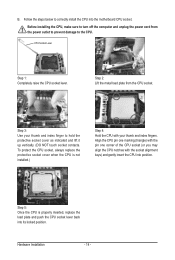
B. Before installing the CPU, make sure to turn off the computer and unplug the power cord from the CPU socket. Step 2: Lift the metal load plate from the power outlet to prevent damage to hold the protective socket cover as indicated and lift it up vertically. (DO NOT touch socket contacts. Align the CPU pin one marking (triangle) with the pin one corner of the CPU socket (or you may align the CPU notches with your thumb and index finger to the CPU. CPU Socket Lever Step 1: Completely raise the CPU socket lever. To protect the CPU socket, always replace the protective socket cover...
B. Before installing the CPU, make sure to turn off the computer and unplug the power cord from the CPU socket. Step 2: Lift the metal load plate from the power outlet to prevent damage to hold the protective socket cover as indicated and lift it up vertically. (DO NOT touch socket contacts. Align the CPU pin one marking (triangle) with the pin one corner of the CPU socket (or you may align the CPU notches with your thumb and index finger to the CPU. CPU Socket Lever Step 1: Completely raise the CPU socket lever. To protect the CPU socket, always replace the protective socket cover...

Manual
Page 15
If the push pin is inserted as the example cooler.) Step 1: Apply an even and thin layer of thermal grease on the surface of the CPU cooler to the CPU fan header (CPU_FAN) on the motherboard. Hardware Installation Direction of the Arrow Sign on the Male Push Pin Male Push Pin The Top of Female Push Pin Female Push Pin Step 2: Before installing the cooler, note the direction of the arrow sign on the male push pin. (Turning the push pin along the direction of the motherboard. Step 4: You should hear a "click" when pushing down on the push pins diagonally. Use extreme care...
If the push pin is inserted as the example cooler.) Step 1: Apply an even and thin layer of thermal grease on the surface of the CPU cooler to the CPU fan header (CPU_FAN) on the motherboard. Hardware Installation Direction of the Arrow Sign on the Male Push Pin Male Push Pin The Top of Female Push Pin Female Push Pin Step 2: Before installing the cooler, note the direction of the arrow sign on the male push pin. (Turning the push pin along the direction of the motherboard. Step 4: You should hear a "click" when pushing down on the push pins diagonally. Use extreme care...
Manual
Page 16
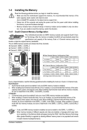
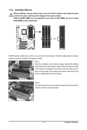
... Four Modules DS/SS DS/SS - - Dual Channel-1. ory is recommended that memory of the same capacity, brand, speed, and chips be used. (Go to GIGABYTE's website for the latest memory support list.) • Always turn off the computer and unplug the power cord from the power outlet before installing the...
... Four Modules DS/SS DS/SS - - Dual Channel-1. ory is recommended that memory of the same capacity, brand, speed, and chips be used. (Go to GIGABYTE's website for the latest memory support list.) • Always turn off the computer and unplug the power cord from the power outlet before installing the...
Manual
Page 17
DDR3 and DDR2 DIMMs are not compatible to each other or DDR DIMMs. Be sure to install DDR3 DIMMs on the socket. Notch DDR3 DIMM A DDR3 memory module has a notch, so it can only fit in the picture on the left, place your memory modules in the memory sockets. Step 2: The clips at both ends of the memory, push down on the memory and insert it vertically into place when the memory module is securely inserted. - 17 - 1-4-2 Installing a Memory Before installing a memory module, make sure to turn off the computer and unplug the power cord from the power outlet to prevent damage to ...
DDR3 and DDR2 DIMMs are not compatible to each other or DDR DIMMs. Be sure to install DDR3 DIMMs on the socket. Notch DDR3 DIMM A DDR3 memory module has a notch, so it can only fit in the picture on the left, place your memory modules in the memory sockets. Step 2: The clips at both ends of the memory, push down on the memory and insert it vertically into place when the memory module is securely inserted. - 17 - 1-4-2 Installing a Memory Before installing a memory module, make sure to turn off the computer and unplug the power cord from the power outlet to prevent damage to ...
Manual
Page 18
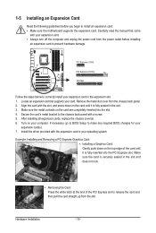
If necessary, go to BIOS Setup to the chassis back panel with your expansion card. • Always turn off the computer and unplug the power cord from the power outlet before you begin to release the card and then pull the card straight up from the chassis back panel. 2. Locate an expansion slot that came with a screw. 5. Secure the card's metal bracket to make any required BIOS changes for your operating system. Make sure the card is securely seated in the slot and does not rock. • Removing the Card: Press the white latch at the end of the card until it is...
If necessary, go to BIOS Setup to the chassis back panel with your expansion card. • Always turn off the computer and unplug the power cord from the power outlet before you begin to release the card and then pull the card straight up from the chassis back panel. 2. Locate an expansion slot that came with a screw. 5. Secure the card's metal bracket to make any required BIOS changes for your operating system. Make sure the card is securely seated in the slot and does not rock. • Removing the Card: Press the white latch at the end of the card until it is...
Manual
Page 19
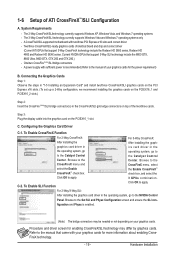
Current NVIDIA GPUs that support 3-Way CrossFireX technology include the Radeon HD 3800 series, Radeon HD 4800 and Radeon HD 58XX series. Browse to the Set SLI and Physx Configuration screen and ensure the SLI con- C-2. Browse to the CrossFireX menu and select the Enable CrossFireX™ check box. The 2-Way CrossFireX/SLItechnology currently supports Windows XP, Windows Vista, and Windows 7 operating systems - To Enable CrossFireX Function For 2-Way CrossFireX: After installing the graphics card driver in the operating system, go to the manual of identical brand and ...
Current NVIDIA GPUs that support 3-Way CrossFireX technology include the Radeon HD 3800 series, Radeon HD 4800 and Radeon HD 58XX series. Browse to the Set SLI and Physx Configuration screen and ensure the SLI con- C-2. Browse to the CrossFireX menu and select the Enable CrossFireX™ check box. The 2-Way CrossFireX/SLItechnology currently supports Windows XP, Windows Vista, and Windows 7 operating systems - To Enable CrossFireX Function For 2-Way CrossFireX: After installing the graphics card driver in the operating system, go to the manual of identical brand and ...
