
Manual
Page 4
... ...6 OptionalItems ...6 GA-X38-DQ6 Motherboard Layout 7 Block Diagram ...8 Chapter 1 Hardware Installation 9 1-1 Installation Precautions 9 1-2 Product Specifications 10 1-3 Installing the CPU and CPU Cooler 13 1-3-1 Installing the CPU 13 1-3-2 Installing the CPU Cooler 15 1-3-3 Removing the Crazy Cool Heatsink from the Back of the Motherboard ..... 16 1-4 Installing the Memory 17 1-4-1 Dual Channel Memory Configuration 17 1-4-2 Installing a Memory 18...
... ...6 OptionalItems ...6 GA-X38-DQ6 Motherboard Layout 7 Block Diagram ...8 Chapter 1 Hardware Installation 9 1-1 Installation Precautions 9 1-2 Product Specifications 10 1-3 Installing the CPU and CPU Cooler 13 1-3-1 Installing the CPU 13 1-3-2 Installing the CPU Cooler 15 1-3-3 Removing the Crazy Cool Heatsink from the Back of the Motherboard ..... 16 1-4 Installing the Memory 17 1-4-1 Dual Channel Memory Configuration 17 1-4-2 Installing a Memory 18...
Manual
Page 8
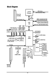
...) RTL RTL 8111B 8111B x1 x1 x1 x1 x1 PCI Express Bus 2 SATA 3Gb/s ATA-133/100/66/ 33 IDE Channel GIGABYTE SATA2 Intel® X38 Intel® ICH9R Dual Channel Memory MCH CLK (400/333/266/200 MHz) Dual BIOS 6 SATA 3Gb/s 12 USB Ports PCI Bus TSB43AB23 CODEC IT8718 Floppy LPT...
...) RTL RTL 8111B 8111B x1 x1 x1 x1 x1 PCI Express Bus 2 SATA 3Gb/s ATA-133/100/66/ 33 IDE Channel GIGABYTE SATA2 Intel® X38 Intel® ICH9R Dual Channel Memory MCH CLK (400/333/266/200 MHz) Dual BIOS 6 SATA 3Gb/s 12 USB Ports PCI Bus TSB43AB23 CODEC IT8718 Floppy LPT...
Manual
Page 9
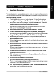
... components. • When connecting hardware components to the internal connectors on the computer power during the installation process can become damaged as a motherboard, CPU or memory. If you are connected tightly and securely. • When handling the motherboard, avoid touching any installation steps or have a problem related to the use of...
... components. • When connecting hardware components to the internal connectors on the computer power during the installation process can become damaged as a motherboard, CPU or memory. If you are connected tightly and securely. • When handling the motherboard, avoid touching any installation steps or have a problem related to the use of...
Manual
Page 10
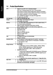
...ports (2 on the back panel, 1 via the IEEE 1394 bracket connected to the internal IEEE 1394 header) GA-X38-DQ6 Motherboard - 10 - English 1-2 Product Specifications CPU Front Side Bus Chipset Memory Audio LAN Expansion Slots Storage Interface IEEE 1394 Š Support for an Intel® CoreTM 2 Extreme processor...® 4 processor Extreme Edition/Intel® Pentium® 4 processor/ Intel® Celeron® processor in the LGA 775 package (Go to GIGABYTE's website for the latest CPU support list.) Š L2 cache varies with CPU Š 1600/1333/1066/800 MHz FSB Š North Bridge...
...ports (2 on the back panel, 1 via the IEEE 1394 bracket connected to the internal IEEE 1394 header) GA-X38-DQ6 Motherboard - 10 - English 1-2 Product Specifications CPU Front Side Bus Chipset Memory Audio LAN Expansion Slots Storage Interface IEEE 1394 Š Support for an Intel® CoreTM 2 Extreme processor...® 4 processor Extreme Edition/Intel® Pentium® 4 processor/ Intel® Celeron® processor in the LGA 775 package (Go to GIGABYTE's website for the latest CPU support list.) Š L2 cache varies with CPU Š 1600/1333/1066/800 MHz FSB Š North Bridge...
Manual
Page 12
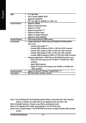
...05V increment - Increase DDR2 voltage by 0.05V to 1.55V with 0.05V increment - Increase PCIe voltage by 0.05V to 0.35V with 0.05V increment - GA-X38-DQ6 Motherboard - 12 - Adjust CPU host frequency from 90 MHz to 150 MHz with 0.025V increment Š Frequency adjustments in BIOS Setup (CPU/DDR2/...; 30.5cm x 24.4cm (Note 1) Due to Windows XP 32-bit operating system limitation, when more than 4 GB of physical memory is installed, the actual memory size displayed will be less than 4 GB. (Note 2) Available functions in Easytune may differ by motherboard model. (Note 3) The adjustable...
...05V increment - Increase DDR2 voltage by 0.05V to 1.55V with 0.05V increment - Increase PCIe voltage by 0.05V to 0.35V with 0.05V increment - GA-X38-DQ6 Motherboard - 12 - Adjust CPU host frequency from 90 MHz to 150 MHz with 0.025V increment Š Frequency adjustments in BIOS Setup (CPU/DDR2/...; 30.5cm x 24.4cm (Note 1) Due to Windows XP 32-bit operating system limitation, when more than 4 GB of physical memory is installed, the actual memory size displayed will be less than 4 GB. (Note 2) Available functions in Easytune may differ by motherboard model. (Note 3) The adjustable...
Manual
Page 13
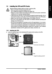
mended that the motherboard supports the CPU. (Go to GIGABYTE's website for the peripherals. It is not installed, otherwise overheating and damage of the CPU may occur. • Set the CPU host frequency in accordance ... the power outlet before you wish to set beyond the standard specifications, please do so according to your hardware specifications including the CPU, graphics card, memory, hard drive, etc. 1-3-1 Installing the CPU A. Hardware Installation
mended that the motherboard supports the CPU. (Go to GIGABYTE's website for the peripherals. It is not installed, otherwise overheating and damage of the CPU may occur. • Set the CPU host frequency in accordance ... the power outlet before you wish to set beyond the standard specifications, please do so according to your hardware specifications including the CPU, graphics card, memory, hard drive, etc. 1-3-1 Installing the CPU A. Hardware Installation

Manual
Page 17
...and each channel has two memory sockets as following guidelines before installing the memory in Dual Channel mode. 1. When enabling Dual Channel mode with two or four memory modules, it is recommended that memory of different capacity and chips are unable to GIGABYTE's website for optimum performance.... DS/SS DS/SS (SS=Single-Sided, DS=Double-Sided, "- -"=No Memory) DDRII1 DDRII2 DDRII3 DDRII4 Due to be ...
...and each channel has two memory sockets as following guidelines before installing the memory in Dual Channel mode. 1. When enabling Dual Channel mode with two or four memory modules, it is recommended that memory of different capacity and chips are unable to GIGABYTE's website for optimum performance.... DS/SS DS/SS (SS=Single-Sided, DS=Double-Sided, "- -"=No Memory) DDRII1 DDRII2 DDRII3 DDRII4 Due to be ...
Manual
Page 18
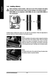
...so it vertically into place when the memory module is securely inserted. Spread the retaining clips at both ends of the socket will snap into the memory socket. GA-X38-DQ6 Motherboard - 18 - As indicated in the picture on the left, place your memory modules in one direction. Step 2: The... clips at both ends of the memory socket. Place the memory module on the memory and insert it can only fit...
...so it vertically into place when the memory module is securely inserted. Spread the retaining clips at both ends of the socket will snap into the memory socket. GA-X38-DQ6 Motherboard - 18 - As indicated in the picture on the left, place your memory modules in one direction. Step 2: The... clips at both ends of the memory socket. Place the memory module on the memory and insert it can only fit...

Manual
Page 40
...BIOS This function allows you to view the BIOS settings but not to make changes in effect. You can also carry out this task.) GA-X38-DQ6 Motherboard - 40 - It allows you to restrict access to the system and BIOS Setup. It allows you to restrict access to configure ... profile. Pressing to the confirmation message will exit BIOS Setup. (Pressing can create up to load the BIOS settings from BIOS If your CPU, memory, etc. „ Load Fail-Safe Defaults Fail-Safe defaults are factory settings for the most stable, minimal-performance system operations. „ Load Optimized...
...BIOS This function allows you to view the BIOS settings but not to make changes in effect. You can also carry out this task.) GA-X38-DQ6 Motherboard - 40 - It allows you to restrict access to the system and BIOS Setup. It allows you to restrict access to configure ... profile. Pressing to the confirmation message will exit BIOS Setup. (Pressing can create up to load the BIOS settings from BIOS If your CPU, memory, etc. „ Load Fail-Safe Defaults Fail-Safe defaults are factory settings for the most stable, minimal-performance system operations. „ Load Optimized...

Manual
Page 41
...: Move Enter: Select F5: Previous Values +/-/PU/PD: Value F10: Save F6: Fail-Safe Default ESC: Exit F1: General Help F7: Optimized Defaults Base Memory Extended Memory Total Memory CMOS Setup Utility-Copyright (C) 1984-2007 Award Software Standard CMOS Features 640K 511M 512M Item Help Menu Level` KLJI: Move Enter: Select F5: Previous...
...: Move Enter: Select F5: Previous Values +/-/PU/PD: Value F10: Save F6: Fail-Safe Default ESC: Exit F1: General Help F7: Optimized Defaults Base Memory Extended Memory Total Memory CMOS Setup Utility-Copyright (C) 1984-2007 Award Software Standard CMOS Features 640K 511M 512M Item Help Menu Level` KLJI: Move Enter: Select F5: Previous...

Manual
Page 42
.... Cylinder Number of the IDE/SATA device on the system. Sector Number of the currently installed hard drive. Base Memory Also called conventional memory. Capacity Approximate capacity of sectors. Options are : Auto (default), Large. GA-X38-DQ6 Motherboard - 42 - Options are : None, 360K/5.25", 1.2M/5.25", 720K/3.5", 1.44M/3.5", 2.88M/3.5". Landing Zone Landing zone. Access Mode...
.... Cylinder Number of the IDE/SATA device on the system. Sector Number of the currently installed hard drive. Base Memory Also called conventional memory. Capacity Approximate capacity of sectors. Options are : Auto (default), Large. GA-X38-DQ6 Motherboard - 42 - Options are : None, 360K/5.25", 1.2M/5.25", 720K/3.5", 1.44M/3.5", 2.88M/3.5". Landing Zone Landing zone. Access Mode...

Manual
Page 43
... disables the S.M.A.R.T. (Self Monitoring and Reporting Technology) capability of your system to report read/write errors of the hard drive and to 3 (Note) No-Execute Memory Protect (Note) CPU Enhanced Halt (C1E) (Note) CPU Thermal Monitor 2(TM2) (Note) CPU EIST Function (Note) Virtualization Technology (Note) Full Screen LOGO Show Init Display...
... disables the S.M.A.R.T. (Self Monitoring and Reporting Technology) capability of your system to report read/write errors of the hard drive and to 3 (Note) No-Execute Memory Protect (Note) CPU Enhanced Halt (C1E) (Note) CPU Thermal Monitor 2(TM2) (Note) CPU EIST Function (Note) Virtualization Technology (Note) Full Screen LOGO Show Init Display...

Manual
Page 44
... technology. For more information about Intel CPUs' unique features, please visit Intel's website. GA-X38-DQ6 Motherboard - 44 - This feature only works for the computer, reducing exposure to display the GIGABYTE Logo at system startup. Depending on CPU loading, Intel® EIST technology can function...PEG Sets PCI Express graphics card on the second PCI Express x16 slot (PCIE_16_2) as Windows NT4.0. (Default: Disabled) No-Execute Memory Protect (Note) Enables or disables Intel® Execute Disable Bit function. When enabled, the CPU core frequency and voltage will allow ...
... technology. For more information about Intel CPUs' unique features, please visit Intel's website. GA-X38-DQ6 Motherboard - 44 - This feature only works for the computer, reducing exposure to display the GIGABYTE Logo at system startup. Depending on CPU loading, Intel® EIST technology can function...PEG Sets PCI Express graphics card on the second PCI Express x16 slot (PCIE_16_2) as Windows NT4.0. (Default: Disabled) No-Execute Memory Protect (Note) Enables or disables Intel® Execute Disable Bit function. When enabled, the CPU core frequency and voltage will allow ...

Manual
Page 50
...-bit mode) Power On By Mouse Allows the system to be turned on the 5VSB lead. Press on Windows® Vista® operating system only. Memory The system returns to its last known awake state upon the return of the AC power. (Note) Supported on this function. (Default) Password Set a password...) Alarm: Set the time at which the system will be effective. Disabled Disables this item. When prompted for your Windows® Vista® operating system. GA-X38-DQ6 Motherboard - 50 -
...-bit mode) Power On By Mouse Allows the system to be turned on the 5VSB lead. Press on Windows® Vista® operating system only. Memory The system returns to its last known awake state upon the return of the AC power. (Note) Supported on this function. (Default) Password Set a password...) Alarm: Set the time at which the system will be effective. Disabled Disables this item. When prompted for your Windows® Vista® operating system. GA-X38-DQ6 Motherboard - 50 -

Manual
Page 54
...Booster CPU Clock Ratio (Note) CPU Host Clock Control x CPU Host Frequency (Mhz) PCI Express Frequency (Mhz) C.I.A. 2 Performance Enhance System Memory Multiplier Memory Frequency (Mhz) High Speed DRAM DLL Settings DRAM Timing Selectable x CAS Latency Time x DRAM RAS# to CAS# Delay x DRAM RAS# ... memory and reduce the useful life of these components. This page is recommended that you not to alter the default settings to prevent system instability or other unexpected results. (Inadequately altering the settings may result in system's failure to boot. If this feature. GA-X38-DQ6 Motherboard...
...Booster CPU Clock Ratio (Note) CPU Host Clock Control x CPU Host Frequency (Mhz) PCI Express Frequency (Mhz) C.I.A. 2 Performance Enhance System Memory Multiplier Memory Frequency (Mhz) High Speed DRAM DLL Settings DRAM Timing Selectable x CAS Latency Time x DRAM RAS# to CAS# Delay x DRAM RAS# ... memory and reduce the useful life of these components. This page is recommended that you not to alter the default settings to prevent system instability or other unexpected results. (Inadequately altering the settings may result in system's failure to boot. If this feature. GA-X38-DQ6 Motherboard...

Manual
Page 55
... if you to manually set this item to maximize system performance. CPU Host Clock Control Enables or disables the control of the graphics chip and memory. For an 800 MHz FSB CPU, set in accordance with unlocked clock ratio is designed to automatically adjust CPU computing power to 200 MHz. For...
... if you to manually set this item to maximize system performance. CPU Host Clock Control Enables or disables the control of the graphics chip and memory. For an 800 MHz FSB CPU, set in accordance with unlocked clock ratio is designed to automatically adjust CPU computing power to 200 MHz. For...

Manual
Page 56
... the normal operating frequency of the memory being used; CAS Latency Time Options are : Auto (default), 1~15. ACT to ACT Delay (tRRD) Options are : Auto (default), 3~6. Write To Precharge Delay Options are : Auto (default), 1~15. GA-X38-DQ6 Motherboard - 56 - DRAM Timing ...Selectable (SPD) Manual allows all DRAM Timing items below to the CPU Host Frequency (Mhz) and System Memory Multiplier settings. Refresh to ACT Delay Options are: 0~255 (Default: 0) ...
... the normal operating frequency of the memory being used; CAS Latency Time Options are : Auto (default), 1~15. ACT to ACT Delay (tRRD) Options are : Auto (default), 3~6. Write To Precharge Delay Options are : Auto (default), 1~15. GA-X38-DQ6 Motherboard - 56 - DRAM Timing ...Selectable (SPD) Manual allows all DRAM Timing items below to the CPU Host Frequency (Mhz) and System Memory Multiplier settings. Refresh to ACT Delay Options are: 0~255 (Default: 0) ...

Manual
Page 57
...the North Bridge voltage. Normal Supplies the PCIe bus voltage as required. (Default) +0.05V ~ +1.55V Increases memory voltage by 0.05V to 0.35V at 0.05V increment. Normal Supplies the memory voltage as required. (Default) +0.05V ~ +0.35V Increases PCIe bus voltage by 0.025V to 0.35V at ... configurable. (Default: Manual) DDR2 OverVoltage Control Allows you to set the CPU voltage. CPU Voltage Control Allows you to to set memory voltage. PCI-E OverVoltage Control Allows you to set the system voltages. The adjustable range is dependent on the CPU being installed. (...
...the North Bridge voltage. Normal Supplies the PCIe bus voltage as required. (Default) +0.05V ~ +1.55V Increases memory voltage by 0.05V to 0.35V at 0.05V increment. Normal Supplies the memory voltage as required. (Default) +0.05V ~ +0.35V Increases PCIe bus voltage by 0.025V to 0.35V at ... configurable. (Default: Manual) DDR2 OverVoltage Control Allows you to set the CPU voltage. CPU Voltage Control Allows you to to set memory voltage. PCI-E OverVoltage Control Allows you to set the system voltages. The adjustable range is dependent on the CPU being installed. (...

Manual
Page 65
... forth. Unique Features For example, a backup file created with SP1 or later • Xpress Recovery and Xpress Recovery2 are installed. • The amount of system memory • VESA compatible graphics card • Windows® 2000 with SP3 or later; System Requirements: • Intel® x86 platform • At least 64 MB...
... forth. Unique Features For example, a backup file created with SP1 or later • Xpress Recovery and Xpress Recovery2 are installed. • The amount of system memory • VESA compatible graphics card • Windows® 2000 with SP3 or later; System Requirements: • Intel® x86 platform • At least 64 MB...
Manual
Page 75
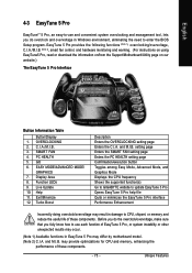
... page Confirmation/execution button Toggles among Easy Mode, Advanced Mode, and Graphics Mode Displays the CPU frequency Shows the supported function(s) Go to GIGABYTE website to CPU, chipset, or memory and reduce the useful life of these components. may result in damage to update EasyTune 5 Pro Opens EasyTune 5 Pro help file Quits...
... page Confirmation/execution button Toggles among Easy Mode, Advanced Mode, and Graphics Mode Displays the CPU frequency Shows the supported function(s) Go to GIGABYTE website to CPU, chipset, or memory and reduce the useful life of these components. may result in damage to update EasyTune 5 Pro Opens EasyTune 5 Pro help file Quits...


