
Manual
Page 1
GA-X38-DQ6 LGA775 socket motherboard for Intel® CoreTM processor family/ Intel® Pentium® processor family/Intel® Celeron® processor family User's Manual Rev. 1002 12ME-X38DQ6-1002R
GA-X38-DQ6 LGA775 socket motherboard for Intel® CoreTM processor family/ Intel® Pentium® processor family/Intel® Celeron® processor family User's Manual Rev. 1002 12ME-X38DQ6-1002R

Manual
Page 2
Motherboard GA-X38-DQ6 Sept. 3, 2007 Motherboard GA-X38-DQ6 Sept. 3, 2007
Motherboard GA-X38-DQ6 Sept. 3, 2007 Motherboard GA-X38-DQ6 Sept. 3, 2007

Manual
Page 4
Table of Contents Box Contents ...6 OptionalItems ...6 GA-X38-DQ6 Motherboard Layout 7 Block Diagram ...8 Chapter 1 Hardware Installation 9 1-1 Installation Precautions 9 1-2 Product Specifications 10 1-3 Installing the CPU and CPU Cooler 13 1-3-1 Installing the CPU 13 1-3-2 Installing the ...
Table of Contents Box Contents ...6 OptionalItems ...6 GA-X38-DQ6 Motherboard Layout 7 Block Diagram ...8 Chapter 1 Hardware Installation 9 1-1 Installation Precautions 9 1-2 Product Specifications 10 1-3 Installing the CPU and CPU Cooler 13 1-3-1 Installing the CPU 13 1-3-2 Installing the ...
Manual
Page 6
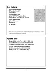
... (Part No. 12CF1-1LP001-01R) - 6 - The box contents are for reference only and the actual items shall depend on product package you obtain. Box Contents GA-X38-DQ6 motherboard Motherboard driver disk User's Manual Quick Installation Guide Intel® LGA775 CPU Installation Guide One IDE cable and one floppy disk drive cable Four...
... (Part No. 12CF1-1LP001-01R) - 6 - The box contents are for reference only and the actual items shall depend on product package you obtain. Box Contents GA-X38-DQ6 motherboard Motherboard driver disk User's Manual Quick Installation Guide Intel® LGA775 CPU Installation Guide One IDE cable and one floppy disk drive cable Four...

Manual
Page 7
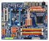
GA-X38-DQ6 Motherboard Layout KB_MS RCA_SPDIF USB_1394_1 SYS_FAN1 ATX_12V_2X LGA775 CPU_FAN PCIE_12V ATX USB_1394_2 USB_LAN USB_LAN2 PWR_FAN RTL8111B Intel® X38 AUDIO F_AUDIO PCIE_1 NB_FAN RTL8111B GA-X38-DQ6 FDD PCIE_16_1 DDRII1 DDRII2 DDRII3 DDRII4 CODEC CD_IN PCIE_2 PCIE_3 BP_BIOS MAIN_BIOS BAT PCIE_16_2 CLR_CMOS Intel® ICH9R SATAII0 IDE SATAII1 SPDIF_O PCI1 IT8718 PCI2 LPT CI COM TPM F_1394 F_USB2 F_USB1 TSB43AB23 GIGABYTE SATA2 SATAII4 SATAII2 GSATAIIA PWR_LED SPDIF_IN SYS_FAN2 F_PANEL SATAII5 SATAII3 GSATAIIB - 7 -
GA-X38-DQ6 Motherboard Layout KB_MS RCA_SPDIF USB_1394_1 SYS_FAN1 ATX_12V_2X LGA775 CPU_FAN PCIE_12V ATX USB_1394_2 USB_LAN USB_LAN2 PWR_FAN RTL8111B Intel® X38 AUDIO F_AUDIO PCIE_1 NB_FAN RTL8111B GA-X38-DQ6 FDD PCIE_16_1 DDRII1 DDRII2 DDRII3 DDRII4 CODEC CD_IN PCIE_2 PCIE_3 BP_BIOS MAIN_BIOS BAT PCIE_16_2 CLR_CMOS Intel® ICH9R SATAII0 IDE SATAII1 SPDIF_O PCI1 IT8718 PCI2 LPT CI COM TPM F_1394 F_USB2 F_USB1 TSB43AB23 GIGABYTE SATA2 SATAII4 SATAII2 GSATAIIA PWR_LED SPDIF_IN SYS_FAN2 F_PANEL SATAII5 SATAII3 GSATAIIB - 7 -
Manual
Page 10
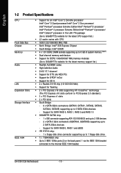
...GIGABYTE SATA2 chip: - 1 x IDE connector supporting ATA-133/100/66/33 and up to 2 IDE devices - 2 x SATA 3 Gb/s connectors (GSATAIIA, GSATAIIB) supporting up to 6 SATA 3Gb/s devices - TSB43AB23 chip Š Up to 3 IEEE 1394a ports (2 on the back panel, 1 via the IEEE 1394 bracket connected to the internal IEEE 1394 header) GA-X38-DQ6...memory (Note 1) Š Dual channel memory architecture Š Support for DDR2 1066/800/667 MHz memory modules (Go to GIGABYTE's website for the latest memory support list.) Š Realtek ALC889A codec Š High Definition Audio Š 2/4/5.1/7.1-channel &#...
...GIGABYTE SATA2 chip: - 1 x IDE connector supporting ATA-133/100/66/33 and up to 2 IDE devices - 2 x SATA 3 Gb/s connectors (GSATAIIA, GSATAIIB) supporting up to 6 SATA 3Gb/s devices - TSB43AB23 chip Š Up to 3 IEEE 1394a ports (2 on the back panel, 1 via the IEEE 1394 bracket connected to the internal IEEE 1394 header) GA-X38-DQ6...memory (Note 1) Š Dual channel memory architecture Š Support for DDR2 1066/800/667 MHz memory modules (Go to GIGABYTE's website for the latest memory support list.) Š Realtek ALC889A codec Š High Definition Audio Š 2/4/5.1/7.1-channel &#...
Manual
Page 12
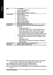
... frequency - Adjust PCI Express x16 frequency from 100 MHz to 700 MHz with 0.05V increment - Increase FSB voltage by 0.05V to 0.35V with 0.05V increment - GA-X38-DQ6 Motherboard - 12 - English BIOS Unique Features Bundled Software Overclocking Operating System Form Factor Š 2 x 8 Mbit flash Š Use of licensed AWARD BIOS Š Support for...
... frequency - Adjust PCI Express x16 frequency from 100 MHz to 700 MHz with 0.05V increment - Increase FSB voltage by 0.05V to 0.35V with 0.05V increment - GA-X38-DQ6 Motherboard - 12 - English BIOS Unique Features Bundled Software Overclocking Operating System Form Factor Š 2 x 8 Mbit flash Š Use of licensed AWARD BIOS Š Support for...
Manual
Page 14
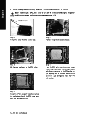
... CPU socket (or you may align the CPU notches with your thumb and index fingers. Step 3: Lift the metal load plate on the CPU socket. GA-X38-DQ6 Motherboard - 14 - CPU Socket Lever Step 1: Completely raise the CPU socket lever.
... CPU socket (or you may align the CPU notches with your thumb and index fingers. Step 3: Lift the metal load plate on the CPU socket. GA-X38-DQ6 Motherboard - 14 - CPU Socket Lever Step 1: Completely raise the CPU socket lever.

Manual
Page 16
... provided with the motherboard from the back of the board. On the front side of the board, align the spring nut removed in a safe place. GA-X38-DQ6 Motherboard - 16 - The Crazy Cool Heatsink Tools needed: 1. Use extreme care when installing or removing the Crazy Cool heatsink. Always keep the removed screws in...
... provided with the motherboard from the back of the board. On the front side of the board, align the spring nut removed in a safe place. GA-X38-DQ6 Motherboard - 16 - The Crazy Cool Heatsink Tools needed: 1. Use extreme care when installing or removing the Crazy Cool heatsink. Always keep the removed screws in...
Manual
Page 18
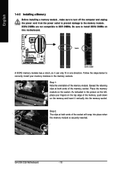
... ends of the memory module. Place the memory module on the socket. Step 1: Note the orientation of the socket will snap into the memory socket. GA-X38-DQ6 Motherboard - 18 - As indicated in the picture on the left, place your memory modules in one direction. DDR2 DIMMs are not compatible to DDR DIMMs...
... ends of the memory module. Place the memory module on the socket. Step 1: Note the orientation of the socket will snap into the memory socket. GA-X38-DQ6 Motherboard - 18 - As indicated in the picture on the left, place your memory modules in one direction. DDR2 DIMMs are not compatible to DDR DIMMs...
Manual
Page 20
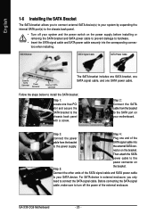
... the bracket. the external SATA con- For SATA device in external enclosure, you to connect external SATA device(s) to the chassis back panel with a screw. GA-X38-DQ6 Motherboard - 20 - Step 3: Step 4: Connect the power Plug one end of the external enclosure. Step 2: Connect the SATA cable from the bracket SATA signal cable...
... the bracket. the external SATA con- For SATA device in external enclosure, you to connect external SATA device(s) to the chassis back panel with a screw. GA-X38-DQ6 Motherboard - 20 - Step 3: Step 4: Connect the power Plug one end of the external enclosure. Step 2: Connect the SATA cable from the bracket SATA signal cable...
Manual
Page 22
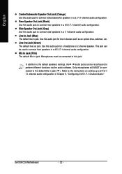
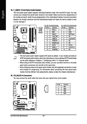
... be reconfigured to the instructions on setting up a 2/4/5.1/ 7.1-channel audio configuration in Chapter 5, "Configuring 2/4/5.1/7.1-Channel Audio." Line Out Jack (Green) The default line out jack. GA-X38-DQ6 Motherboard - 22 - Line In Jack (Blue) The default line in a 7.1-channel audio configuration. Side Speaker Out Jack (Gray) Use this audio jack to the default...
... be reconfigured to the instructions on setting up a 2/4/5.1/ 7.1-channel audio configuration in Chapter 5, "Configuring 2/4/5.1/7.1-Channel Audio." Line Out Jack (Green) The default line out jack. GA-X38-DQ6 Motherboard - 22 - Line In Jack (Blue) The default line in a 7.1-channel audio configuration. Side Speaker Out Jack (Gray) Use this audio jack to the default...
Manual
Page 24
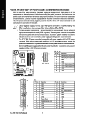
... (Only for 2x4 pin 12V) 3 GND 4 GND 5 +12V (Only for 2x4 pin 12V) 6 +12V (Only for 2x4 pin 12V) 7 +12V 8 +12V 12 24 1 13 ATX GA-X38-DQ6 Motherboard ATX : Pin No. 1 2 3 4 5 6 7 8 9 10 11 12 Definition 3.3V 3.3V GND +5V GND +5V GND Power Good 5V SB(stand by the CPU manufacturer when...
... (Only for 2x4 pin 12V) 3 GND 4 GND 5 +12V (Only for 2x4 pin 12V) 6 +12V (Only for 2x4 pin 12V) 7 +12V 8 +12V 12 24 1 13 ATX GA-X38-DQ6 Motherboard ATX : Pin No. 1 2 3 4 5 6 7 8 9 10 11 12 Definition 3.3V 3.3V GND +5V GND +5V GND Power Good 5V SB(stand by the CPU manufacturer when...

Manual
Page 26
... a floppy disk drive. English 7) PCIE_12V (Power Connector) This power connector can supply extra power to the PCI Express x16 slots on the connector. 34 33 2 1 GA-X38-DQ6 Motherboard - 26 - Connect the power supply cable to this connector when using two graphics cards. The types of floppy disk drives supported are: 360 KB...
... a floppy disk drive. English 7) PCIE_12V (Power Connector) This power connector can supply extra power to the PCI Express x16 slots on the connector. 34 33 2 1 GA-X38-DQ6 Motherboard - 26 - Connect the power supply cable to this connector when using two graphics cards. The types of floppy disk drives supported are: 360 KB...

Manual
Page 28
English 11) GSATAIIA/GSATAIIB (SATA 3Gb/s Connectors, Controlled by GIGABYTE SATA2, Purple) The SATA connectors conform to Chapter 5, "Configuring SATA Hard Drive(s)," for instructions on configuring a RAID array. Refer to SATA 3Gb/s standard and are ... connect a system power LED on when the system is operating. The GIGABYTE SATA2 controller supports RAID 0 and RAID 1. The LED keeps blinking when the system is in S1 sleep state. System Status LED S0 On S1 Blinking S3/S4/S5 Off GA-X38-DQ6 Motherboard - 28 - Each SATA connector supports a single SATA device. Definition...
English 11) GSATAIIA/GSATAIIB (SATA 3Gb/s Connectors, Controlled by GIGABYTE SATA2, Purple) The SATA connectors conform to Chapter 5, "Configuring SATA Hard Drive(s)," for instructions on configuring a RAID array. Refer to SATA 3Gb/s standard and are ... connect a system power LED on when the system is operating. The GIGABYTE SATA2 controller supports RAID 0 and RAID 1. The LED keeps blinking when the system is in S1 sleep state. System Status LED S0 On S1 Blinking S3/S4/S5 Off GA-X38-DQ6 Motherboard - 28 - Each SATA connector supports a single SATA device. Definition...
Manual
Page 30
... contact the chassis manufacturer. 15) CD_IN (CD In Connector) You may connect your optical drive to the header. 1 Pin No. Definition 1 CD-L 2 GND 3 GND 4 CD-R GA-X38-DQ6 Motherboard - 30 - You may connect the audio cable that has separated connectors on how to activate AC'97 functioninality via the audio software in Chapter...
... contact the chassis manufacturer. 15) CD_IN (CD In Connector) You may connect your optical drive to the header. 1 Pin No. Definition 1 CD-L 2 GND 3 GND 4 CD-R GA-X38-DQ6 Motherboard - 30 - You may connect the audio cable that has separated connectors on how to activate AC'97 functioninality via the audio software in Chapter...

Manual
Page 32
... can provide one end of the cable to USB 2.0/1.1 specification. The IEEE 1394a header can provide two USB ports via an optional IEEE 1394a bracket. GA-X38-DQ6 Motherboard - 32 -
... can provide one end of the cable to USB 2.0/1.1 specification. The IEEE 1394a header can provide two USB ports via an optional IEEE 1394a bracket. GA-X38-DQ6 Motherboard - 32 -

Manual
Page 34
... of the positive side (+) and the negative side (-) of the battery (the positive side should face up). • Used batteries must be lost. Turn off . GA-X38-DQ6 Motherboard - 34 - You may be handled in accordance with an equivalent one. English 22) COM (Serial Port Header) The COM header can provide one minute...
... of the positive side (+) and the negative side (-) of the battery (the positive side should face up). • Used batteries must be lost. Turn off . GA-X38-DQ6 Motherboard - 34 - You may be handled in accordance with an equivalent one. English 22) COM (Serial Port Header) The COM header can provide one minute...

Manual
Page 36
English GA-X38-DQ6 Motherboard - 36 -
English GA-X38-DQ6 Motherboard - 36 -
Manual
Page 38
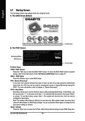
... restart, the device boot order will directly boot from the device configured in Boot Menu is effective for X38-DQ6 D19 . . . . : BIOS Setup : XpressRecovery2 : Boot Menu : Qflash 08/17/2007-X38-ICH9-6A79OG0QC-00 Function Keys Function Keys: : POST Screen Press the key to set the first boot device...can be based on page 44. : BIOS Setup Press the key to enter BIOS Setup. : Xpress Recovery2 If you to show the BIOS POST screen. GA-X38-DQ6 Motherboard - 38 - A. The system will still be used for subsequent access to back up arrow key < > or the down arrow key< > ...
... restart, the device boot order will directly boot from the device configured in Boot Menu is effective for X38-DQ6 D19 . . . . : BIOS Setup : XpressRecovery2 : Boot Menu : Qflash 08/17/2007-X38-ICH9-6A79OG0QC-00 Function Keys Function Keys: : POST Screen Press the key to set the first boot device...can be based on page 44. : BIOS Setup Press the key to enter BIOS Setup. : Xpress Recovery2 If you to show the BIOS POST screen. GA-X38-DQ6 Motherboard - 38 - A. The system will still be used for subsequent access to back up arrow key < > or the down arrow key< > ...

