Manual
Page 1
GA-P67A-UD3-B3 GA-PH67A-UD3-B3 GA-PH67-UD3-B3 LGA1155 socket motherboard for Intel® Core™ i7 processors/ Intel® Core™ i5 processors/Intel® Core™ i3 processors/ Intel® Pentium® processors/Intel® Celeron® processors User's Manual Rev. 1101
GA-P67A-UD3-B3 GA-PH67A-UD3-B3 GA-PH67-UD3-B3 LGA1155 socket motherboard for Intel® Core™ i7 processors/ Intel® Core™ i5 processors/Intel® Core™ i3 processors/ Intel® Pentium® processors/Intel® Celeron® processors User's Manual Rev. 1101
Manual
Page 2
Motherboard GA-P67A-UD3-B3/GA-PH67A-UD3-B3/GA-PH67-UD3-B3 Jan. 14, 2011 Motherboard GA-P67A-UD3-B3/ GA-PH67A-UD3-B3/ GA-PH67-UD3-B3 Jan. 14, 2011
Motherboard GA-P67A-UD3-B3/GA-PH67A-UD3-B3/GA-PH67-UD3-B3 Jan. 14, 2011 Motherboard GA-P67A-UD3-B3/ GA-PH67A-UD3-B3/ GA-PH67-UD3-B3 Jan. 14, 2011
Manual
Page 3
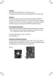
... prior notice. For product-related information, check on our website at: http://www.gigabyte.com Identifying Your Motherboard Revision The revision number on your motherboard revision before updating motherboard BIOS, drivers, or when looking for technical information. For example, "REV: 1.0"... means the revision of the motherboard is the property of this manual may be reproduced, copied, translated, transmitted, or published in this : "REV: X.X." Disclaimer Information in this manual may be made by GIGABYTE without GIGABYTE's prior written permission. The trademarks ...
... prior notice. For product-related information, check on our website at: http://www.gigabyte.com Identifying Your Motherboard Revision The revision number on your motherboard revision before updating motherboard BIOS, drivers, or when looking for technical information. For example, "REV: 1.0"... means the revision of the motherboard is the property of this manual may be reproduced, copied, translated, transmitted, or published in this : "REV: X.X." Disclaimer Information in this manual may be made by GIGABYTE without GIGABYTE's prior written permission. The trademarks ...
Manual
Page 4
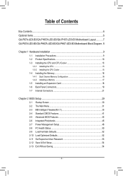
Table of Contents Box Contents...6 Optional Items...6 GA-P67A-UD3-B3/GA-PH67A-UD3-B3/GA-PH67-UD3-B3 Motherboard Layout............7 GA-P67A-UD3-B3/GA-PH67A-UD3-B3/GA-PH67-UD3-B3 Motherboard Block Diagram.. 8 Chapter 1 Hardware Installation 9 1-1 Installation Precautions 9 1-2 Product Specifications 10 1-3 Installing the CPU and CPU Cooler 13 1-3-1 Installing the CPU 13 1-3-2 Installing the CPU Cooler ...
Table of Contents Box Contents...6 Optional Items...6 GA-P67A-UD3-B3/GA-PH67A-UD3-B3/GA-PH67-UD3-B3 Motherboard Layout............7 GA-P67A-UD3-B3/GA-PH67A-UD3-B3/GA-PH67-UD3-B3 Motherboard Block Diagram.. 8 Chapter 1 Hardware Installation 9 1-1 Installation Precautions 9 1-2 Product Specifications 10 1-3 Installing the CPU and CPU Cooler 13 1-3-1 Installing the CPU 13 1-3-2 Installing the CPU Cooler ...
Manual
Page 6
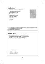
.... 12CR1-1UB030-5*R) 2-port SATA power cable (Part No. 12CF1-2SERPW-0*R) COM port cable (Part No. 12CF1-1CM001-3*R) j k l Only for GA-P67A-UD3-B3 Only for GA-PH67A-UD3-B3 Only for GA-PH67-UD3-B3 - 6 - Box Contents GA-P67A-UD3-B3, GA-PH67A-UD3-B3, or GA-PH67-UD3-B3 motherboard Motherboard driver disk User's Manual Quick Installation Guide Two SATA cableskl Four SATA cablesj I/O Shield • The box contents above are...
.... 12CR1-1UB030-5*R) 2-port SATA power cable (Part No. 12CF1-2SERPW-0*R) COM port cable (Part No. 12CF1-1CM001-3*R) j k l Only for GA-P67A-UD3-B3 Only for GA-PH67A-UD3-B3 Only for GA-PH67-UD3-B3 - 6 - Box Contents GA-P67A-UD3-B3, GA-PH67A-UD3-B3, or GA-PH67-UD3-B3 motherboard Motherboard driver disk User's Manual Quick Installation Guide Two SATA cableskl Four SATA cablesj I/O Shield • The box contents above are...
Manual
Page 7
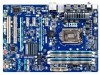
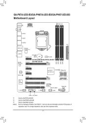
GA-P67A-UD3-B3/GA-PH67A-UD3-B3/GA-PH67-UD3-B3 Motherboard Layout KB_MS_USB R_SPDIF ATX_12V_2X4 R_USB_2 LGA1155 PHASE LED R_USB_1 R_USB30 ATX USB_LAN Renesas D720200jk AUDIO Realtek RTL8111E CODEC SPDIF_O iTE IT8728 F_AUDIO SYS_FAN1 PCIEX1_1 (Note) BAT CPU_FAN PCIEX16 GA-P67A-UD3-B3/GA-PH67A-UD3-B3/ GA-PH67-UD3-B3 DDR3_1 DDR3_2 DDR3_3 DDR3_4 PCIEX1_2 PCIEX1_3 PCIEX4 PCI1 PCI2 F_USB2 Intel® P67j M_BIOS B_BIOS Intel® H67kl SATA3_0...
GA-P67A-UD3-B3/GA-PH67A-UD3-B3/GA-PH67-UD3-B3 Motherboard Layout KB_MS_USB R_SPDIF ATX_12V_2X4 R_USB_2 LGA1155 PHASE LED R_USB_1 R_USB30 ATX USB_LAN Renesas D720200jk AUDIO Realtek RTL8111E CODEC SPDIF_O iTE IT8728 F_AUDIO SYS_FAN1 PCIEX1_1 (Note) BAT CPU_FAN PCIEX16 GA-P67A-UD3-B3/GA-PH67A-UD3-B3/ GA-PH67-UD3-B3 DDR3_1 DDR3_2 DDR3_3 DDR3_4 PCIEX1_2 PCIEX1_3 PCIEX4 PCI1 PCI2 F_USB2 Intel® P67j M_BIOS B_BIOS Intel® H67kl SATA3_0...
Manual
Page 8
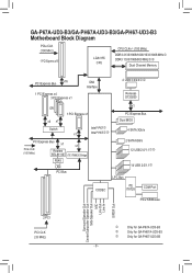
GA-P67A-UD3-B3/GA-PH67A-UD3-B3/GA-PH67-UD3-B3 Motherboard Block Diagram PCIe CLK (100 MHz) 1 PCI Express x16 LGA1155 CPU CPU CLK+/- (100 MHz) DDR3 2133/1866/1600/1333/1066 MHzj DDR3 1333/1066/.../Mouse Surround Speaker Out Center/Subwoofer Speaker Out Side Speaker Out MIC Line Out Line In S/PDIF Out 2 PCI PCI CLK (33 MHz) j k l Only for GA-P67A-UD3-B3 Only for GA-PH67A-UD3-B3 Only for GA-PH67-UD3-B3 - 8 -
GA-P67A-UD3-B3/GA-PH67A-UD3-B3/GA-PH67-UD3-B3 Motherboard Block Diagram PCIe CLK (100 MHz) 1 PCI Express x16 LGA1155 CPU CPU CLK+/- (100 MHz) DDR3 2133/1866/1600/1333/1066 MHzj DDR3 1333/1066/.../Mouse Surround Speaker Out Center/Subwoofer Speaker Out Side Speaker Out MIC Line Out Line In S/PDIF Out 2 PCI PCI CLK (33 MHz) j k l Only for GA-P67A-UD3-B3 Only for GA-PH67A-UD3-B3 Only for GA-PH67-UD3-B3 - 8 -
Manual
Page 9
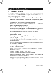
...please verify that all cables and power connectors of your hardware components are connected tightly and securely. • When handling the motherboard, avoid touching any installation steps or have it on top of an antistatic pad or within an electrostatic shielding container. •... Before unplugging the power supply cable from the power outlet before installing or removing the motherboard or other hardware components. • When connecting hardware components to the internal connectors on the computer power during the installation ...
...please verify that all cables and power connectors of your hardware components are connected tightly and securely. • When handling the motherboard, avoid touching any installation steps or have it on top of an antistatic pad or within an electrostatic shielding container. •... Before unplugging the power supply cable from the power outlet before installing or removing the motherboard or other hardware components. • When connecting hardware components to the internal connectors on the computer power during the installation ...
Manual
Page 12
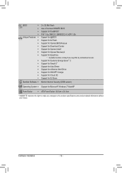
... Charge Support for Cloud OC Support for Q-Share Norton Internet Security (OEM version) Operating System w Support for EasyTune * Available functions in EasyTune may differ by motherboard model. Hardware Installation - 12 -
... Charge Support for Cloud OC Support for Q-Share Norton Internet Security (OEM version) Operating System w Support for EasyTune * Available functions in EasyTune may differ by motherboard model. Hardware Installation - 12 -
Manual
Page 13
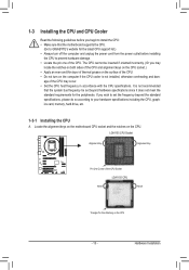
Hardware Installation Locate the alignment keys on the motherboard CPU socket and the notches on the CPU - 13 - age of the CPU may locate the notches on both sides of the CPU and alignment ... standard requirements for the latest CPU support list.) • Always turn on the computer if the CPU cooler is not recommended that the motherboard supports the CPU. (Go to GIGABYTE's website for the peripherals. It is not installed, otherwise overheating and dam- If you may occur. • Set the CPU host frequency...
Hardware Installation Locate the alignment keys on the motherboard CPU socket and the notches on the CPU - 13 - age of the CPU may locate the notches on both sides of the CPU and alignment ... standard requirements for the latest CPU support list.) • Always turn on the computer if the CPU cooler is not recommended that the motherboard supports the CPU. (Go to GIGABYTE's website for the peripherals. It is not installed, otherwise overheating and dam- If you may occur. • Set the CPU host frequency...
Manual
Page 14
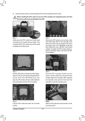
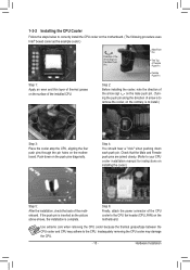
...) with your thumb to lift up the front edge (next to lightly replace the load plate. Step 5: Push the CPU socket lever back into the motherboard CPU socket. Step 4: Once the CPU is not installed.) Step 3: Hold the CPU with the pin one hand to hold the socket lever and use...
...) with your thumb to lift up the front edge (next to lightly replace the load plate. Step 5: Push the CPU socket lever back into the motherboard CPU socket. Step 4: Once the CPU is not installed.) Step 3: Hold the CPU with the pin one hand to hold the socket lever and use...
Manual
Page 15
...Intel® boxed cooler as the picture above shows, the installation is complete. Step 4: You should hear a "click" when pushing down on the motherboard. Use extreme care when removing the CPU cooler because the thermal grease/tape between the CPU cooler and CPU may damage the CPU. - 15 - Hardware... installing the cooler, note the direction of the arrow sign on the male push pin. (Turning the push pin along the direction of the motherboard. Push down each push pin. Check that the Male and Female push pins are joined closely. (Refer to your CPU cooler installation manual for...
...Intel® boxed cooler as the picture above shows, the installation is complete. Step 4: You should hear a "click" when pushing down on the motherboard. Use extreme care when removing the CPU cooler because the thermal grease/tape between the CPU cooler and CPU may damage the CPU. - 15 - Hardware... installing the cooler, note the direction of the arrow sign on the male push pin. (Turning the push pin along the direction of the motherboard. Push down each push pin. Check that the Male and Female push pins are joined closely. (Refer to your CPU cooler installation manual for...
Manual
Page 16
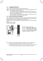
...memory, switch the direction. If you begin to install the memory: • Make sure that the motherboard supports the memory. Dual Channel Memory Configuration This motherboard provides four DDR3 memory sockets and supports Dual Channel Technology. 1-4 Installing the Memory 1-4-1 Read the ...memory mode will automatically detect the specifications and capacity of the same capacity, brand, speed, and chips be used . (Go to GIGABYTE's website for optimum performance. DS/SS DDR3_4 - Dual Channel mode cannot be installed in Dual Channel mode. 1. Hardware Installation - 16...
...memory, switch the direction. If you begin to install the memory: • Make sure that the motherboard supports the memory. Dual Channel Memory Configuration This motherboard provides four DDR3 memory sockets and supports Dual Channel Technology. 1-4 Installing the Memory 1-4-1 Read the ...memory mode will automatically detect the specifications and capacity of the same capacity, brand, speed, and chips be used . (Go to GIGABYTE's website for optimum performance. DS/SS DDR3_4 - Dual Channel mode cannot be installed in Dual Channel mode. 1. Hardware Installation - 16...
Manual
Page 17
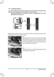
..., make sure to turn off the computer and unplug the power cord from the power outlet to prevent damage to install DDR3 DIMMs on this motherboard. Hardware Installation
..., make sure to turn off the computer and unplug the power cord from the power outlet to prevent damage to install DDR3 DIMMs on this motherboard. Hardware Installation
Manual
Page 18
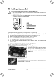
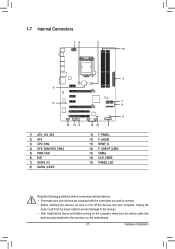
... expansion slot. 1. PCI Express x1 Slot PCI Express x16 Slot PCI Slot Follow the steps below to install an expansion card: • Make sure the motherboard supports the expansion card. Hardware Installation - 18 - Install the driver provided with a screw. 5.
... expansion slot. 1. PCI Express x1 Slot PCI Express x16 Slot PCI Slot Follow the steps below to install an expansion card: • Make sure the motherboard supports the expansion card. Hardware Installation - 18 - Install the driver provided with a screw. 5.
Manual
Page 19
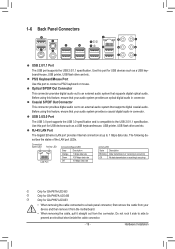
...to 1 Gbps data rate. USB 3.0/2.0 Port The USB 3.0 port supports the USB 3.0 specification and is occurring j k l Only for GA-P67A-UD3-B3 Only for GA-PH67A-UD3-B3 Only for USB devices such as a USB keyboard/mouse, USB printer, USB flash drive and etc. Use this port to prevent an ... system provides an optical digital audio in connector. Hardware Installation Use this feature, ensure that your device and then remove it from the motherboard. • When removing the cable, pull it side to side to connect a PS/2 keyboard or mouse. The following describes the...
...to 1 Gbps data rate. USB 3.0/2.0 Port The USB 3.0 port supports the USB 3.0 specification and is occurring j k l Only for GA-P67A-UD3-B3 Only for GA-PH67A-UD3-B3 Only for USB devices such as a USB keyboard/mouse, USB printer, USB flash drive and etc. Use this port to prevent an ... system provides an optical digital audio in connector. Hardware Installation Use this feature, ensure that your device and then remove it from the motherboard. • When removing the cable, pull it side to side to connect a PS/2 keyboard or mouse. The following describes the...
Manual
Page 21
... devices and your devices are compliant with the connectors you wish to connect. • Before installing the devices, be sure to the connector on the motherboard. - 21 -
... devices and your devices are compliant with the connectors you wish to connect. • Before installing the devices, be sure to the connector on the motherboard. - 21 -
Manual
Page 22
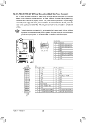
...-pin ATX) GND (Only for 2x12-pin ATX) Hardware Installation - 22 - If the 12V power connector is turned off and all the components on the motherboard. If a power supply is recommended that a power supply that does not provide the required power, the result can lead to an unstable or unbootable system...
...-pin ATX) GND (Only for 2x12-pin ATX) Hardware Installation - 22 - If the 12V power connector is turned off and all the components on the motherboard. If a power supply is recommended that a power supply that does not provide the required power, the result can lead to an unstable or unbootable system...
Manual
Page 23
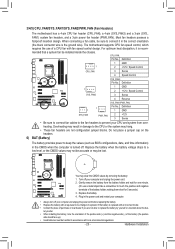
... if the battery is recom- Replace the battery. 4. Danger of the battery holder, making them short for one . 3/4/5) CPU_FAN/SYS_FAN1/SYS_FAN2/PWR_FAN (Fan Headers) The motherboard has a 4-pin CPU fan header (CPU_FAN), a 4-pin (SYS_FAN2) and a 3-pin (SYS_ FAN1) system fan headers, and a 3-pin power fan header (PWR_FAN... or the CMOS values may not be accurate or may clear the CMOS values by yourself or uncertain about the bat- The motherboard supports CPU fan speed control, which requires the use a metal object like a screwdriver to prevent your computer and unplug the power cord. 2....
... if the battery is recom- Replace the battery. 4. Danger of the battery holder, making them short for one . 3/4/5) CPU_FAN/SYS_FAN1/SYS_FAN2/PWR_FAN (Fan Headers) The motherboard has a 4-pin CPU fan header (CPU_FAN), a 4-pin (SYS_FAN2) and a 3-pin (SYS_ FAN1) system fan headers, and a 3-pin power fan header (PWR_FAN... or the CMOS values may not be accurate or may clear the CMOS values by yourself or uncertain about the bat- The motherboard supports CPU fan speed control, which requires the use a metal object like a screwdriver to prevent your computer and unplug the power cord. 2....

Manual
Page 26
... wire instead of the front and back panel audio connections simultane- If your expansion card. Pin No. Make sure the wire assignments of the motherboard header. If you wish to connect an HDMI display to work or even damage it. Definition Pin No. For information about connecting the front ... 9 Line Out (L) 10 GND 10 NC • The front panel audio header supports HD audio by expansion cards) for digital audio output from your motherboard to your graphics card if you want to mute the back panel audio (only supported when using an HD front panel audio module), refer to...
... wire instead of the front and back panel audio connections simultane- If your expansion card. Pin No. Make sure the wire assignments of the motherboard header. If you wish to connect an HDMI display to work or even damage it. Definition Pin No. For information about connecting the front ... 9 Line Out (L) 10 GND 10 NC • The front panel audio header supports HD audio by expansion cards) for digital audio output from your motherboard to your graphics card if you want to mute the back panel audio (only supported when using an HD front panel audio module), refer to...


