
Manual
Page 7
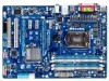
GA-P67A-D3-B3 Motherboard Layout KB_MS_USB ATX_12V CPU_FAN COMA LPT OPTICAL LGA1155 R_USB30/20 ATX USB_LAN AUDIO Etron EJ168 SYS_FAN1 SPDIF_O BAT F_AUDIO PCIEX1_1 Realtek RTL8111E PCIEX16 GA-P67A-D3-B3 PCIEX1_2 CODEC PCIEX1_3 Intel® P67 iTE IT8728 PCIEX4 PCI1 PCI2 SYS_FAN2 PCIe to PCI Bridge DDR3_4 DDR3_2 DDR3_3 DDR3_1 PWR_FAN M_BIOS B_BIOS SATA3_0 SATA3_1 SATA2_2 SATA2_3 SATA2_4 SATA2_5 F_PANELCLR_CMOS TPM F_USB3 F_USB2 F_USB1 - 7 -
GA-P67A-D3-B3 Motherboard Layout KB_MS_USB ATX_12V CPU_FAN COMA LPT OPTICAL LGA1155 R_USB30/20 ATX USB_LAN AUDIO Etron EJ168 SYS_FAN1 SPDIF_O BAT F_AUDIO PCIEX1_1 Realtek RTL8111E PCIEX16 GA-P67A-D3-B3 PCIEX1_2 CODEC PCIEX1_3 Intel® P67 iTE IT8728 PCIEX4 PCI1 PCI2 SYS_FAN2 PCIe to PCI Bridge DDR3_4 DDR3_2 DDR3_3 DDR3_1 PWR_FAN M_BIOS B_BIOS SATA3_0 SATA3_1 SATA2_2 SATA2_3 SATA2_4 SATA2_5 F_PANELCLR_CMOS TPM F_USB3 F_USB2 F_USB1 - 7 -

Manual
Page 12
... for Xpress Install ŠŠ Support for Xpress Recovery2 ŠŠ Support for EasyTune * Available functions in EasyTune may differ by motherboard model. ŠŠ Support for Smart 6™ ŠŠ Support for Auto Green ŠŠ Support for eXtreme Hard Drive...OEM version) Operating System ŠŠ Support for Microsoft® Windows 7/Vista/XP Form Factor ŠŠ ATX Form Factor; 30.5cm x 21.5cm * GIGABYTE reserves the right to make any changes to the product specifications and product-related information without prior notice. Hardware ...
... for Xpress Install ŠŠ Support for Xpress Recovery2 ŠŠ Support for EasyTune * Available functions in EasyTune may differ by motherboard model. ŠŠ Support for Smart 6™ ŠŠ Support for Auto Green ŠŠ Support for eXtreme Hard Drive...OEM version) Operating System ŠŠ Support for Microsoft® Windows 7/Vista/XP Form Factor ŠŠ ATX Form Factor; 30.5cm x 21.5cm * GIGABYTE reserves the right to make any changes to the product specifications and product-related information without prior notice. Hardware ...

Manual
Page 21
... make sure the device cable has been securely attached to turn off the devices and your computer. 1-7 Internal Connectors 1 3 4 10 11 4 14 12 2 6 5 7 8 13 9 1) ATX_12V 2) ATX 3) CPU_FAN 4) SYS_FAN1/2 5) PWR_FAN 6) BAT 7) SATA3_0/1 8) SATA2_2/3/4/5 9) F_PANEL 10) F_AUDIO 11) SPDIF_O 12) F_USB1/F_USB2/F_USB3 13) CLR_CMOS 14) TPM Read the following guidelines before turning... sure your devices are compliant with the connectors you wish to connect. •• Before installing the devices, be sure to the connector on the motherboard. - 21 -
... make sure the device cable has been securely attached to turn off the devices and your computer. 1-7 Internal Connectors 1 3 4 10 11 4 14 12 2 6 5 7 8 13 9 1) ATX_12V 2) ATX 3) CPU_FAN 4) SYS_FAN1/2 5) PWR_FAN 6) BAT 7) SATA3_0/1 8) SATA2_2/3/4/5 9) F_PANEL 10) F_AUDIO 11) SPDIF_O 12) F_USB1/F_USB2/F_USB3 13) CLR_CMOS 14) TPM Read the following guidelines before turning... sure your devices are compliant with the connectors you wish to connect. •• Before installing the devices, be sure to the connector on the motherboard. - 21 -

Manual
Page 22
... power to the power connector in the correct orientation. If the 12V power connector is turned off and all the components on the motherboard. 1/2) ATX_12V/ATX (2x2 12V Power Connector and 2x12 Main Power Connector) With the use of the power connector, the power supply can withstand high...that can supply enough stable power to an unstable or unbootable system. 3 4 1 2 ATX_12V ATX_12V: Pin No. 1 2 3 4 Definition GND GND +12V +12V 12 24 1 13 ATX ATX: Pin No. 1 2 3 4 5 6 7 8 9 10 11 12 Definition Pin No. 3.3V 13 3.3V 14 GND 15 +5V 16 GND 17 +5V 18 GND 19 ...
... power to the power connector in the correct orientation. If the 12V power connector is turned off and all the components on the motherboard. 1/2) ATX_12V/ATX (2x2 12V Power Connector and 2x12 Main Power Connector) With the use of the power connector, the power supply can withstand high...that can supply enough stable power to an unstable or unbootable system. 3 4 1 2 ATX_12V ATX_12V: Pin No. 1 2 3 4 Definition GND GND +12V +12V 12 24 1 13 ATX ATX: Pin No. 1 2 3 4 5 6 7 8 9 10 11 12 Definition Pin No. 3.3V 13 3.3V 14 GND 15 +5V 16 GND 17 +5V 18 GND 19 ...

Manual
Page 96
... system startup, follow the troubleshooting procedure below to the motherboard. START Turn off the power. Secure the CPU cooler No on the power to the CPU securely. No Correctly insert the memory into the memory socket. Connect the ATX main power cable and the 12V power cable. The ...A (Continued...) Appendix - 96 - Yes Isolate the short circuit. Make sure the graphics card is attached to start the computer. Make sure the motherboard does not short-circuit with the chassis or other metal objects. Remove all peripherals, connecting cables, and power cord etc.
... system startup, follow the troubleshooting procedure below to the motherboard. START Turn off the power. Secure the CPU cooler No on the power to the CPU securely. No Correctly insert the memory into the memory socket. Connect the ATX main power cable and the 12V power cable. The ...A (Continued...) Appendix - 96 - Yes Isolate the short circuit. Make sure the graphics card is attached to start the computer. Make sure the motherboard does not short-circuit with the chassis or other metal objects. Remove all peripherals, connecting cables, and power cord etc.


