
Manual
Page 1
...the Intel Matrix Storage Console, with a simple click of data. (Note 3) If you manually build a non-RAID 0 array, you have to load the SATA controller driver first. Using GIGABYTE eXtreme Hard Drive (X.H.D) Instructions:(Note 2) Before launching X.H.D, make sure the newly added harddrive ...risk of hardware damage or lost of a button, X.H.D helps to enhance your needs and hardware components. 3. eXtreme Hard Drive (X.H.D) With GIGABYTE eXtreme Hard Drive (X.H.D)(Note 1), users can quickly configure a RAIDready system for RAID 0 when a new SATA drive is recommended that already ...
...the Intel Matrix Storage Console, with a simple click of data. (Note 3) If you manually build a non-RAID 0 array, you have to load the SATA controller driver first. Using GIGABYTE eXtreme Hard Drive (X.H.D) Instructions:(Note 2) Before launching X.H.D, make sure the newly added harddrive ...risk of hardware damage or lost of a button, X.H.D helps to enhance your needs and hardware components. 3. eXtreme Hard Drive (X.H.D) With GIGABYTE eXtreme Hard Drive (X.H.D)(Note 1), users can quickly configure a RAIDready system for RAID 0 when a new SATA drive is recommended that already ...

Manual
Page 1
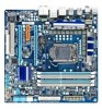
GA-P55M-UD4 LGA1156 socket motherboard for Intel® Core™ i7 processor family/ Intel® Core™ i5 processor family User's Manual Rev. 1001 12ME-P55MUD4-1001R
GA-P55M-UD4 LGA1156 socket motherboard for Intel® Core™ i7 processor family/ Intel® Core™ i5 processor family User's Manual Rev. 1001 12ME-P55MUD4-1001R

Manual
Page 3
... included with the product. For example, "REV: 1.0" means the revision of this manual are legally registered to the specifications and features in this manual may be made by any form or by GIGABYTE without GIGABYTE's prior written permission. Disclaimer Information in this manual is protected by copyright laws and is 1.0. For instructions on how to...
... included with the product. For example, "REV: 1.0" means the revision of this manual are legally registered to the specifications and features in this manual may be made by any form or by GIGABYTE without GIGABYTE's prior written permission. Disclaimer Information in this manual is protected by copyright laws and is 1.0. For instructions on how to...
Manual
Page 5
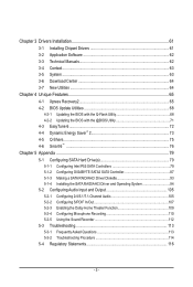
Chapter 3 Drivers Installation 61 3-1 Installing Chipset Drivers 61 3-2 Application Software 62 3-3 Technical Manuals 62 3-4 Contact...63 3-5 System...63 3-6 Download Center 64 3-7 New Utilities...64 Chapter 4 Unique Features 65 4-1 Xpress Recovery2...Q-Share...75 4-6 Smart 6™ ...76 Chapter 5 Appendix...79 5-1 Configuring SATA Hard Drive(s 79 5-1-1 Configuring Intel P55 SATA Controllers 79 5-1-2 Configuring GIGABYTE SATA2 SATA Controller 87 5-1-3 Making a SATA RAID/AHCI Driver Diskette 93 5-1-4 Installing the SATA RAID/AHCI Driver and Operating System 94 5-2 Configuring Audio ...
Chapter 3 Drivers Installation 61 3-1 Installing Chipset Drivers 61 3-2 Application Software 62 3-3 Technical Manuals 62 3-4 Contact...63 3-5 System...63 3-6 Download Center 64 3-7 New Utilities...64 Chapter 4 Unique Features 65 4-1 Xpress Recovery2...Q-Share...75 4-6 Smart 6™ ...76 Chapter 5 Appendix...79 5-1 Configuring SATA Hard Drive(s 79 5-1-1 Configuring Intel P55 SATA Controllers 79 5-1-2 Configuring GIGABYTE SATA2 SATA Controller 87 5-1-3 Making a SATA RAID/AHCI Driver Diskette 93 5-1-4 Installing the SATA RAID/AHCI Driver and Operating System 94 5-2 Configuring Audio ...

Manual
Page 6
Box Contents GA-P55M-UD4 motherboard Motherboard driver disk User's Manual Quick Installation Guide One IDE cable Four SATA 3Gb/s cables I/O Shield 2-Way SLI bridge connector • The box contents above are subject to change without ...
Box Contents GA-P55M-UD4 motherboard Motherboard driver disk User's Manual Quick Installation Guide One IDE cable Four SATA 3Gb/s cables I/O Shield 2-Way SLI bridge connector • The box contents above are subject to change without ...

Manual
Page 9
... circuits and components which can lead to damage to system components as well as a motherboard, CPU or memory. Prior to installation, carefully read the user's manual and follow these procedures: • Prior to installation, do not remove or break motherboard S/N (Serial Number) sticker or warranty sticker provided by unplugging the power...
... circuits and components which can lead to damage to system components as well as a motherboard, CPU or memory. Prior to installation, carefully read the user's manual and follow these procedures: • Prior to installation, do not remove or break motherboard S/N (Serial Number) sticker or warranty sticker provided by unplugging the power...

Manual
Page 15
... the CPU cooler may adhere to the CPU. Check that the Male and Female push pins are joined closely. (Refer to your CPU cooler installation manual for instructions on installing the cooler.) Step 5: After the installation, check the back of the CPU cooler to the CPU fan header (CPU_FAN) on the...
... the CPU cooler may adhere to the CPU. Check that the Male and Female push pins are joined closely. (Refer to your CPU cooler installation manual for instructions on installing the cooler.) Step 5: After the installation, check the back of the CPU cooler to the CPU fan header (CPU_FAN) on the...

Manual
Page 18
... on the card until it is fully seated in the expansion slot. 1. Make sure the card is fully inserted into the slot. 4. Carefully read the manual that supports your expansion card in the slot. 3. If necessary, go to BIOS Setup to install an expansion card: • Make sure the motherboard supports...
... on the card until it is fully seated in the expansion slot. 1. Make sure the card is fully inserted into the slot. 4. Carefully read the manual that supports your expansion card in the slot. 3. If necessary, go to BIOS Setup to install an expansion card: • Make sure the motherboard supports...

Manual
Page 19
... (Note)/SLI bridge connectors - To Enable CrossFireX Function After installing the graphics card driver in the operating system, go to the manual of the two cards. Browse to the Set SLI Configuration screen and ensure the Enable SLI technology check box is recommended (Refer to...and correct driver - A power supply with sufficient power is selected. (Note) The bridge connectors may differ by graphics cards. Browse to the manual that came with two PCI Express x16 slots and correct driver - Step 2: Insert the CrossFire (Note)/SLI bridge connectors in "1-5 Installing an Expansion...
... (Note)/SLI bridge connectors - To Enable CrossFireX Function After installing the graphics card driver in the operating system, go to the manual of the two cards. Browse to the Set SLI Configuration screen and ensure the Enable SLI technology check box is recommended (Refer to...and correct driver - A power supply with sufficient power is selected. (Note) The bridge connectors may differ by graphics cards. Browse to the manual that came with two PCI Express x16 slots and correct driver - Step 2: Insert the CrossFire (Note)/SLI bridge connectors in "1-5 Installing an Expansion...

Manual
Page 29
... purchasing the optional S/PDIF In cable, please contact the local dealer. Hardware Installation For information about connecting the S/PDIF digital audio cable, carefully read the manual for digital audio output from the HDMI display at the same time. 14) SPDIF_I (S/PDIF In Header, White) This header supports digital S/PDIF In and...
... purchasing the optional S/PDIF In cable, please contact the local dealer. Hardware Installation For information about connecting the S/PDIF digital audio cable, carefully read the manual for digital audio output from the HDMI display at the same time. 14) SPDIF_I (S/PDIF In Header, White) This header supports digital S/PDIF In and...

Manual
Page 31
... the power outlet before clearing the CMOS values. • After system restart, go to BIOS Setup to load factory defaults (select Load Optimized Defaults) or manually configure the BIOS settings (refer to change hardware components or conduct hardware testing. Refer to clear the CMOS values (e.g. To enable the Phase LED display...
... the power outlet before clearing the CMOS values. • After system restart, go to BIOS Setup to load factory defaults (select Load Optimized Defaults) or manually configure the BIOS settings (refer to change hardware components or conduct hardware testing. Refer to clear the CMOS values (e.g. To enable the Phase LED display...

Manual
Page 40
... Cruise Increases CPU frequency by 5% or 7% depending on CPU loading. Enabled will allow for 20 seconds to allow the BCLK Frequency(Mhz) item below to manually set in accordance with the CPU specifications. Note: If your system hardware components. The adjustable range is from 100 MHz to... manually set the system memory multiplier. This item is configurable only if the Base Clock(BCLK) Control option is highly dependent on system components, when system...
... Cruise Increases CPU frequency by 5% or 7% depending on CPU loading. Enabled will allow for 20 seconds to allow the BCLK Frequency(Mhz) item below to manually set in accordance with the CPU specifications. Note: If your system hardware components. The adjustable range is from 100 MHz to... manually set the system memory multiplier. This item is configurable only if the Base Clock(BCLK) Control option is highly dependent on system components, when system...

Manual
Page 48
If you wish to enter the parameters manually, refer to the information on this channel. Capacity Approximate capacity of extended memory. Precomp Write precompensation cylinder. Landing Zone Landing zone. If you do not ... , set this item to None so the system will skip the detection of the device during the POST for faster system startup. • Manual Allows you to manually enter the specifications of the hard drive when the hard drive access mode is set to CHS. Total Memory The total amount of cylinders.
If you wish to enter the parameters manually, refer to the information on this channel. Capacity Approximate capacity of extended memory. Precomp Write precompensation cylinder. Landing Zone Landing zone. If you do not ... , set this item to None so the system will skip the detection of the device during the POST for faster system startup. • Manual Allows you to manually enter the specifications of the hard drive when the hard drive access mode is set to CHS. Total Memory The total amount of cylinders.

Manual
Page 61
...; For USB 2.0 driver support under the Windows XP operating system, please install the Windows XP Service Pack 1 or later. Or click Install Single Items to manually select the drivers you wish to install other applications included in Device Manager, please remove the question mark (by right-clicking your mouse and select...
...; For USB 2.0 driver support under the Windows XP operating system, please install the Windows XP Service Pack 1 or later. Or click Install Single Items to manually select the drivers you wish to install other applications included in Device Manager, please remove the question mark (by right-clicking your mouse and select...

Manual
Page 62
Drivers Installation - 62 - You can click the Install button on the right of an item to install it. 3-3 Technical Manuals This page provides GIGABYTE's application guides, content descriptions for this driver disk, and the motherboard manuals. 3-2 Application Software This page displays all the utilities and applications that GIGABYTE develops and some free software.
Drivers Installation - 62 - You can click the Install button on the right of an item to install it. 3-3 Technical Manuals This page provides GIGABYTE's application guides, content descriptions for this driver disk, and the motherboard manuals. 3-2 Application Software This page displays all the utilities and applications that GIGABYTE develops and some free software.

Manual
Page 68
... or a hard drive attached to enter MS-DOS mode. P55M-UD4 D3 . . . . : BIOS Setup : XpressRecovery2 : Boot Menu : Qflash 07/10/2009-P55-7A89RG0MC-00 Because BIOS flashing is saved to enter Q-Flash. 4-2 BIOS Update Utilities GIGABYTE motherboards provide two unique BIOS update tools, Q-Flash™... features the DualBIOS™ design, which enhances protection for the safety and stability of system safety, users cannot update the backup BIOS manually. Award Modular BIOS v6.00PG, An Energy Star Ally Copyright (C) 1984-2009, Award Software, Inc. Restart the system. However, ...
... or a hard drive attached to enter MS-DOS mode. P55M-UD4 D3 . . . . : BIOS Setup : XpressRecovery2 : Boot Menu : Qflash 07/10/2009-P55-7A89RG0MC-00 Because BIOS flashing is saved to enter Q-Flash. 4-2 BIOS Update Utilities GIGABYTE motherboards provide two unique BIOS update tools, Q-Flash™... features the DualBIOS™ design, which enhances protection for the safety and stability of system safety, users cannot update the backup BIOS manually. Award Modular BIOS v6.00PG, An Energy Star Ally Copyright (C) 1984-2009, Award Software, Inc. Restart the system. However, ...

Manual
Page 71
...the BIOS file to be flashed matches your motherboard model. Make sure that matches your motherboard model. Unique Features Do not use the G.O.M. (GIGABYTE Online Management) function when using @BIOS. 4. Update the BIOS without Using the Internet Update Function" below. 2. Follow the on -screen ...so may result in a corrupted BIOS or a system that is not present on the @BIOS server site, please manually download the BIOS update file from GIGABYTE's website and follow the instructions in "Update the BIOS without Using the Internet Update Function: Click Update BIOS from File...
...the BIOS file to be flashed matches your motherboard model. Make sure that matches your motherboard model. Unique Features Do not use the G.O.M. (GIGABYTE Online Management) function when using @BIOS. 4. Update the BIOS without Using the Internet Update Function" below. 2. Follow the on -screen ...so may result in a corrupted BIOS or a system that is not present on the @BIOS server site, please manually download the BIOS update file from GIGABYTE's website and follow the instructions in "Update the BIOS without Using the Internet Update Function: Click Update BIOS from File...

Manual
Page 85
...Recovery Disks : Select Disks Strip Size : N/A Capacity : 0.0 GB Sync : Continuous Create Volume [ HELP ] Select a sync option: On Request: volume is updated manually Continuous: volume is updated automatically [hi]-Change [TAB]-Next [ESC]-Previous Menu Figure 11 [ENTER]-Select Step 5: Finally press on the hard drive you want...from the master drive to a previous state. On Request also allows users to restore the master drive to the recovery drive manually using the Update Volume function of the Intel Matrix Storage Console in the system. In the SELECT DISKS box, press on ...
...Recovery Disks : Select Disks Strip Size : N/A Capacity : 0.0 GB Sync : Continuous Create Volume [ HELP ] Select a sync option: On Request: volume is updated manually Continuous: volume is updated automatically [hi]-Change [TAB]-Next [ESC]-Previous Menu Figure 11 [ENTER]-Select Step 5: Finally press on the hard drive you want...from the master drive to a previous state. On Request also allows users to restore the master drive to the recovery drive manually using the Update Volume function of the Intel Matrix Storage Console in the system. In the SELECT DISKS box, press on ...

Manual
Page 100
... Appendix - 100 - If you do not enable automatic rebuild on this stage, you enter the operating system (look for rebuilding detected. Rebuilding applies only to manually rebuild the array in the operating system. The following screen appears, indicating that a RAID volume is being rebuilt). Create RAID Volume[ DEGRADED VOLUME DETECTED3]. Exit...
... Appendix - 100 - If you do not enable automatic rebuild on this stage, you enter the operating system (look for rebuilding detected. Rebuilding applies only to manually rebuild the array in the operating system. The following screen appears, indicating that a RAID volume is being rebuilt). Create RAID Volume[ DEGRADED VOLUME DETECTED3]. Exit...

Manual
Page 105
... retask the Center/Subwoofer speaker out jack to be Side speaker out. • To install a microphone, connect your microphone to the Mic in jack and manually configure the jack for microphone functionality. • Audio signals will appear in the notification area. Appendix For example, in and out) to the following instructions...
... retask the Center/Subwoofer speaker out jack to be Side speaker out. • To install a microphone, connect your microphone to the Mic in jack and manually configure the jack for microphone functionality. • Audio signals will appear in the notification area. Appendix For example, in and out) to the following instructions...


