
Manual
Page 1
...motherboard driver disk. A. To manually set up all motherboard drivers, including the X.H.D utility. Or you run the X.H.D utility, back up a RAID-ready system and configure it for complex and time-consuming configurations. Exits the X.H.D utility: Click Cancel to individually install the X.H.D utility later. Using GIGABYTE...1) The X.H.D utility only supports the SATA controllers integrated in the array. ) 1. eXtreme Hard Drive (X.H.D) With GIGABYTE eXtreme Hard Drive (X.H.D)(Note 1), users can quickly configure a RAIDready system for the Intel SATA controllers. All with ...
...motherboard driver disk. A. To manually set up all motherboard drivers, including the X.H.D utility. Or you run the X.H.D utility, back up a RAID-ready system and configure it for complex and time-consuming configurations. Exits the X.H.D utility: Click Cancel to individually install the X.H.D utility later. Using GIGABYTE...1) The X.H.D utility only supports the SATA controllers integrated in the array. ) 1. eXtreme Hard Drive (X.H.D) With GIGABYTE eXtreme Hard Drive (X.H.D)(Note 1), users can quickly configure a RAIDready system for the Intel SATA controllers. All with ...

Manual
Page 1
GA-P55M-UD4 LGA1156 socket motherboard for Intel® Core™ i7 processor family/ Intel® Core™ i5 processor family User's Manual Rev. 1001 12ME-P55MUD4-1001R
GA-P55M-UD4 LGA1156 socket motherboard for Intel® Core™ i7 processor family/ Intel® Core™ i5 processor family User's Manual Rev. 1001 12ME-P55MUD4-1001R

Manual
Page 3
...may be made by any means without prior notice. For product-related information, check on our website at: http://www.gigabyte.com.tw Identifying Your Motherboard Revision The revision number on our website. Changes to their respective owners. No part of the product, read the User...'s Manual. Check your motherboard looks like this product, GIGABYTE provides the following types of documentations: For quick set-up of this manual may be reproduced, copied, translated, transmitted,...
...may be made by any means without prior notice. For product-related information, check on our website at: http://www.gigabyte.com.tw Identifying Your Motherboard Revision The revision number on our website. Changes to their respective owners. No part of the product, read the User...'s Manual. Check your motherboard looks like this product, GIGABYTE provides the following types of documentations: For quick set-up of this manual may be reproduced, copied, translated, transmitted,...

Manual
Page 4
Table of Contents Box Contents...6 Optional Items...6 GA-P55M-UD4 Motherboard Layout 7 Block Diagram...8 Chapter 1 Hardware Installation 9 1-1 Installation Precautions 9 1-2 Product Specifications 10 1-3 Installing the CPU and CPU Cooler 13 1-3-1 Installing the CPU 13 1-3-2 Installing the CPU ...
Table of Contents Box Contents...6 Optional Items...6 GA-P55M-UD4 Motherboard Layout 7 Block Diagram...8 Chapter 1 Hardware Installation 9 1-1 Installation Precautions 9 1-2 Product Specifications 10 1-3 Installing the CPU and CPU Cooler 13 1-3-1 Installing the CPU 13 1-3-2 Installing the CPU ...

Manual
Page 6
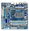
Box Contents GA-P55M-UD4 motherboard Motherboard driver disk User's Manual Quick Installation Guide One IDE cable Four SATA 3Gb/s cables I/O Shield 2-Way SLI bridge connector • The box contents above are subject to change without notice. • The motherboard image is for reference only and the actual items shall depend on the product package you obtain...
Box Contents GA-P55M-UD4 motherboard Motherboard driver disk User's Manual Quick Installation Guide One IDE cable Four SATA 3Gb/s cables I/O Shield 2-Way SLI bridge connector • The box contents above are subject to change without notice. • The motherboard image is for reference only and the actual items shall depend on the product package you obtain...
Manual
Page 7
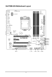
GA-P55M-UD4 Motherboard Layout KB_USB R_SPDIF R_USB_2 CPU_FAN ATX_12V_2X4 LGA1156 PHASE LED ATX PWR_FAN R_USB_1 USB_1394_ESATA USB_LAN RTL8111D AUDIO F_AUDIO SYS_FAN1 CODEC PCIEX4 CD_IN PCIEX8 PCI IT8720 SPDIF_O SPDIF_I B_BIOS M_BIOS BAT PCIEX16 GA-P55M-UD4 DDR3_2 DDR3_1 DDR3_4 DDR3_3 IDE GIGABYTE SATA2 PW_SW TSB43AB23 Intel® P55 CMOS_SW SATA2_4 RST_SW SYS_FAN2 FDD GSATA2_1 GSATA2_0 SATA2_1 SATA2_0 SATA2_3 SATA2_2 F1_1394 F_USB2 F_USB1 F_PANEL - 7 -
GA-P55M-UD4 Motherboard Layout KB_USB R_SPDIF R_USB_2 CPU_FAN ATX_12V_2X4 LGA1156 PHASE LED ATX PWR_FAN R_USB_1 USB_1394_ESATA USB_LAN RTL8111D AUDIO F_AUDIO SYS_FAN1 CODEC PCIEX4 CD_IN PCIEX8 PCI IT8720 SPDIF_O SPDIF_I B_BIOS M_BIOS BAT PCIEX16 GA-P55M-UD4 DDR3_2 DDR3_1 DDR3_4 DDR3_3 IDE GIGABYTE SATA2 PW_SW TSB43AB23 Intel® P55 CMOS_SW SATA2_4 RST_SW SYS_FAN2 FDD GSATA2_1 GSATA2_0 SATA2_1 SATA2_0 SATA2_3 SATA2_2 F1_1394 F_USB2 F_USB1 F_PANEL - 7 -

Manual
Page 9
...These stickers are required for warranty validation. • Always remove the AC power by your hardware components are connected. • To prevent damage to the motherboard, do not have an ESD wrist strap, keep your hands dry and first touch a metal object to eliminate static electricity. • Prior to installing ...the motherboard, please have it on top of an antistatic pad or within the computer casing. • Do not place the computer system on an ...
...These stickers are required for warranty validation. • Always remove the AC power by your hardware components are connected. • To prevent damage to the motherboard, do not have an ESD wrist strap, keep your hands dry and first touch a metal object to eliminate static electricity. • Prior to installing ...the motherboard, please have it on top of an antistatic pad or within the computer casing. • Do not place the computer system on an ...

Manual
Page 12
... with a PCI Express graphics card, the PCIEX16 slot will depend on the CPU/system cooler you install. (Note 5) Available functions in EasyTune may differ by motherboard model.
... with a PCI Express graphics card, the PCIEX16 slot will depend on the CPU/system cooler you install. (Note 5) Available functions in EasyTune may differ by motherboard model.

Manual
Page 13
... the computer and unplug the power cord from the power outlet before you begin to install the CPU: • Make sure that the motherboard supports the CPU. (Go to GIGABYTE's website for the peripherals. It is not installed, otherwise overheating and dam- Locate the alignment keys on the... motherboard CPU socket and the notches on the CPU - 13 - 1-3 Installing the CPU and CPU Cooler Read the following guidelines before installing the CPU ...
... the computer and unplug the power cord from the power outlet before you begin to install the CPU: • Make sure that the motherboard supports the CPU. (Go to GIGABYTE's website for the peripherals. It is not installed, otherwise overheating and dam- Locate the alignment keys on the... motherboard CPU socket and the notches on the CPU - 13 - 1-3 Installing the CPU and CPU Cooler Read the following guidelines before installing the CPU ...

Manual
Page 14
.... Step 1: Gently press the CPU socket lever handle down and away from the power outlet to prevent damage to correctly install the CPU into the motherboard CPU socket. NOTE: Hold the CPU socket lever by the handle, not the lever base portion.
.... Step 1: Gently press the CPU socket lever handle down and away from the power outlet to prevent damage to correctly install the CPU into the motherboard CPU socket. NOTE: Hold the CPU socket lever by the handle, not the lever base portion.

Manual
Page 15
... pin is complete. Check that the Male and Female push pins are joined closely. (Refer to the CPU fan header (CPU_FAN) on the motherboard. Step 6: Finally, attach the power connector of the CPU cooler to your CPU cooler installation manual for instructions on installing the cooler.) Step 5:...the installation is inserted as the example cooler.) Step 1: Apply an even and thin layer of thermal grease on the surface of the motherboard. Inadequately removing the CPU cooler may adhere to the CPU. Use extreme care when removing the CPU cooler because the thermal grease/tape ...
... pin is complete. Check that the Male and Female push pins are joined closely. (Refer to the CPU fan header (CPU_FAN) on the motherboard. Step 6: Finally, attach the power connector of the CPU cooler to your CPU cooler installation manual for instructions on installing the cooler.) Step 5:...the installation is inserted as the example cooler.) Step 1: Apply an even and thin layer of thermal grease on the surface of the motherboard. Inadequately removing the CPU cooler may adhere to the CPU. Use extreme care when removing the CPU cooler because the thermal grease/tape ...

Manual
Page 16
... Memory Configurations Table DDR3_2 DDR3_1 DDR3_4 Two Modules - - After the memory is recommended that the motherboard supports the memory. The four DDR3 memory sockets are unable to insert the memory, switch the direction. 1-4-1 Dual ...Channel Memory Configuration This motherboard provides four DDR3 memory sockets and supports Dual Channel Technology. Four Modules DS/SS DS/SS...the original memory bandwidth. A memory module can be used . (Go to GIGABYTE's website for optimum performance. DS/SS - -
... Memory Configurations Table DDR3_2 DDR3_1 DDR3_4 Two Modules - - After the memory is recommended that the motherboard supports the memory. The four DDR3 memory sockets are unable to insert the memory, switch the direction. 1-4-1 Dual ...Channel Memory Configuration This motherboard provides four DDR3 memory sockets and supports Dual Channel Technology. Four Modules DS/SS DS/SS...the original memory bandwidth. A memory module can be used . (Go to GIGABYTE's website for optimum performance. DS/SS - -

Manual
Page 17
..., make sure to turn off the computer and unplug the power cord from the power outlet to prevent damage to install DDR3 DIMMs on this motherboard. As indicated in the picture on the socket.
..., make sure to turn off the computer and unplug the power cord from the power outlet to prevent damage to install DDR3 DIMMs on this motherboard. As indicated in the picture on the socket.

Manual
Page 18
... slot. After installing all expansion cards, replace the chassis cover(s). 6. If necessary, go to BIOS Setup to install an expansion card: • Make sure the motherboard supports the expansion card. 1-5 Installing an Expansion Card Read the following guidelines before installing an expansion card to correctly install your operating system. Locate an...
... slot. After installing all expansion cards, replace the chassis cover(s). 6. If necessary, go to BIOS Setup to install an expansion card: • Make sure the motherboard supports the expansion card. 1-5 Installing an Expansion Card Read the following guidelines before installing an expansion card to correctly install your operating system. Locate an...

Manual
Page 19
...;/NVIDIA SLI Configuration A. Step 3: Plug the display cable into the graphics card on top of identical brand and chip and correct driver - A CrossFireX/SLI-supported motherboard with sufficient power is recommended (Refer to the CrossFireX menu and ensure the Enable CrossFireX™ check box is selected. (Note) The bridge connectors may...
...;/NVIDIA SLI Configuration A. Step 3: Plug the display cable into the graphics card on top of identical brand and chip and correct driver - A CrossFireX/SLI-supported motherboard with sufficient power is recommended (Refer to the CrossFireX menu and ensure the Enable CrossFireX™ check box is selected. (Note) The bridge connectors may...

Manual
Page 20
... specification, featuring high speed, high bandwidth and hotplug capabilities. Hardware Installation - 20 - Use this feature, ensure that your device and then remove it from the motherboard. • When removing the cable, pull it side to side to an external audio system that supports digital coaxial audio. Connection/ Speed LED Activity LED...
... specification, featuring high speed, high bandwidth and hotplug capabilities. Hardware Installation - 20 - Use this feature, ensure that your device and then remove it from the motherboard. • When removing the cable, pull it side to side to an external audio system that supports digital coaxial audio. Connection/ Speed LED Activity LED...

Manual
Page 22
... 14) SPDIF_I 15) SPDIF_O 16) F_USB1/F_USB2 17) F1_1394 18) PHASE_LED 19) PW_SW 20) CMOS_SW 21) RST_SW Read the following guidelines before turning on the motherboard.
... 14) SPDIF_I 15) SPDIF_O 16) F_USB1/F_USB2 17) F1_1394 18) PHASE_LED 19) PW_SW 20) CMOS_SW 21) RST_SW Read the following guidelines before turning on the motherboard.

Manual
Page 23
... connector. 8 4 5 1 ATX_12V_2X4 ATX_12V_2X4: Pin No. Connect the power supply cable to the CPU. If a power supply is turned off and all the components on the motherboard. Definition 1 GND (Only for 2x4-pin 12V) 2 GND (Only for 2x4-pin 12V) 3 GND 4 GND 5 +12V (Only for 2x4-pin 12V) 6 +12V (... a power supply providing a 2x4 12V and a 2x12 power connector, remove the protective covers from the 12V power connector and the main power connector on the motherboard. Definition 13 3.3V 2 3.3V 14 -12V 3 GND 15 GND 4 +5V 16 PS_ON (soft On/Off) 5 GND 17 GND 6 +5V 18 GND 7 GND 19 ...
... connector. 8 4 5 1 ATX_12V_2X4 ATX_12V_2X4: Pin No. Connect the power supply cable to the CPU. If a power supply is turned off and all the components on the motherboard. Definition 1 GND (Only for 2x4-pin 12V) 2 GND (Only for 2x4-pin 12V) 3 GND 4 GND 5 +12V (Only for 2x4-pin 12V) 6 +12V (... a power supply providing a 2x4 12V and a 2x12 power connector, remove the protective covers from the 12V power connector and the main power connector on the motherboard. Definition 13 3.3V 2 3.3V 14 -12V 3 GND 15 GND 4 +5V 16 PS_ON (soft On/Off) 5 GND 17 GND 6 +5V 18 GND 7 GND 19 ...

Manual
Page 24
3/4/5) CPU_FAN/SYS_FAN1/SYS_FAN2/PWR_FAN (Fan Headers) The motherboard has a 4-pin CPU fan header (CPU_FAN), a 4-pin (SYS_FAN2) and a 3-pin (SYS_FAN1) system fan headers, and a 3-pin power fan header (PWR_FAN). When connecting a fan cable, be ... a stripe of a CPU fan with fan speed control design. The pin 1 of the cable is used to prevent your CPU and system from overheating. The motherboard supports CPU fan speed control, which requires the use of different color. For purchasing the optional floppy disk drive cable, please contact the local dealer...
3/4/5) CPU_FAN/SYS_FAN1/SYS_FAN2/PWR_FAN (Fan Headers) The motherboard has a 4-pin CPU fan header (CPU_FAN), a 4-pin (SYS_FAN2) and a 3-pin (SYS_FAN1) system fan headers, and a 3-pin power fan header (PWR_FAN). When connecting a fan cable, be ... a stripe of a CPU fan with fan speed control design. The pin 1 of the cable is used to prevent your CPU and system from overheating. The motherboard supports CPU fan speed control, which requires the use of different color. For purchasing the optional floppy disk drive cable, please contact the local dealer...

Manual
Page 28
... High Definition audio (HD) and AC'97 audio. For information about connecting the front panel audio module that has separated connectors on both of the motherboard header. You may connect the audio cable that came with your chassis front panel audio module to Chapter 5, "Configuring 2/4/5.1/7.1-Channel Audio." • Some chassis provide...) CD_IN (CD In Connector, Black) You may connect your optical drive to work or even damage it. Incorrect connection between the module connector and the motherboard header will be present on each wire instead of a single plug.
... High Definition audio (HD) and AC'97 audio. For information about connecting the front panel audio module that has separated connectors on both of the motherboard header. You may connect the audio cable that came with your chassis front panel audio module to Chapter 5, "Configuring 2/4/5.1/7.1-Channel Audio." • Some chassis provide...) CD_IN (CD In Connector, Black) You may connect your optical drive to work or even damage it. Incorrect connection between the module connector and the motherboard header will be present on each wire instead of a single plug.


