
Manual
Page 5
... 6™ ...80 4-7 Smart TPM ...83 4-8 Auto Green...84 4-9 eXtreme Hard Drive (X.H.D 85 4-10 Teaming ...86 Chapter 5 Appendix...87 5-1 Configuring SATA Hard Drive(s 87 5-1-1 Configuring Intel P55 SATA Controllers 87 5-1-2 Configuring JMicron JMB362 SATA Controller 95 5-1-3 Configuring Marvell 9128 SATA Controller 101 5-1-4 Making a SATA RAID/AHCI Driver Diskette 106 5-1-5 Installing the SATA...
... 6™ ...80 4-7 Smart TPM ...83 4-8 Auto Green...84 4-9 eXtreme Hard Drive (X.H.D 85 4-10 Teaming ...86 Chapter 5 Appendix...87 5-1 Configuring SATA Hard Drive(s 87 5-1-1 Configuring Intel P55 SATA Controllers 87 5-1-2 Configuring JMicron JMB362 SATA Controller 95 5-1-3 Configuring Marvell 9128 SATA Controller 101 5-1-4 Making a SATA RAID/AHCI Driver Diskette 106 5-1-5 Installing the SATA...
Manual
Page 7
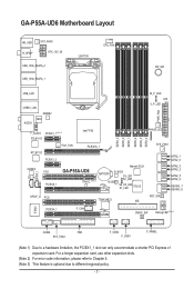
... KB_USB R_SPDIF SYS_FAN3 ATX_12V_2X USB_1394_ESATA_2 USB_1394_ESATA_1 LGA1156 CPU_FAN PW_SW USB_LAN USB30_LAN JMB362 NEC AUDIO F_AUDIO PCIEX1_1 (Note 1) RTL8111D Intel® P55 RTL8111D PCH_FAN PCIEX16_1 CODEC CD_IN SPDIF_I PCIEX1_2 PCI1 PCIEX8_1 GA-P55A-UD6 TPM IC (Note 3) Marvell 9128 BATTERY B_BIOS S3_LED S0_LED M_BIOS S4_S5_LED S1_LED IT8213 SPDIF_O PCI2 TSB43AB23 IDE DDR3_3 DDR3_2 DDR3_1 DDR3_6...
... KB_USB R_SPDIF SYS_FAN3 ATX_12V_2X USB_1394_ESATA_2 USB_1394_ESATA_1 LGA1156 CPU_FAN PW_SW USB_LAN USB30_LAN JMB362 NEC AUDIO F_AUDIO PCIEX1_1 (Note 1) RTL8111D Intel® P55 RTL8111D PCH_FAN PCIEX16_1 CODEC CD_IN SPDIF_I PCIEX1_2 PCI1 PCIEX8_1 GA-P55A-UD6 TPM IC (Note 3) Marvell 9128 BATTERY B_BIOS S3_LED S0_LED M_BIOS S4_S5_LED S1_LED IT8213 SPDIF_O PCI2 TSB43AB23 IDE DDR3_3 DDR3_2 DDR3_1 DDR3_6...
Manual
Page 8
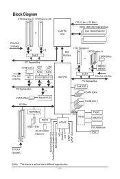
... TSB43AB23 IT8213 3 IEEE 1394a ATA-133/100/66/33 IDE Channel 2 PCI DMI Interface 1 PCI Express x4 3 PCI Express x1 2 SATA 3Gb/s or Intel® P55 JMicron x4 x1 JMB362 Switch PCIe CLK (100 MHz) PCI Express Bus Dual BIOS 6 SATA 3Gb/s 12 USB 2.0/1.1 CODEC LPC Bus IT8720 Floppy COM Port...
... TSB43AB23 IT8213 3 IEEE 1394a ATA-133/100/66/33 IDE Channel 2 PCI DMI Interface 1 PCI Express x4 3 PCI Express x1 2 SATA 3Gb/s or Intel® P55 JMicron x4 x1 JMB362 Switch PCIe CLK (100 MHz) PCI Express Bus Dual BIOS 6 SATA 3Gb/s 12 USB 2.0/1.1 CODEC LPC Bus IT8720 Floppy COM Port...
Manual
Page 10
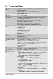
.../Intel® Core™ i5 series processor in the LGA1156 package (Go to GIGABYTE's website for the latest CPU support list.) L3 cache varies with CPU Chipset Intel® P55 Express Chipset Memory 6 x 1.5V DDR3 DIMM sockets supporting up to ...MHz memory modules Support for non-ECC memory modules Support for Extreme Memory Profile (XMP) memory modules (Go to GIGABYTE's website for the latest memory support list.) Audio Realtek ALC889 codec High Definition Audio 2/4/5.1/7.1-channel ...
.../Intel® Core™ i5 series processor in the LGA1156 package (Go to GIGABYTE's website for the latest CPU support list.) L3 cache varies with CPU Chipset Intel® P55 Express Chipset Memory 6 x 1.5V DDR3 DIMM sockets supporting up to ...MHz memory modules Support for non-ECC memory modules Support for Extreme Memory Profile (XMP) memory modules (Go to GIGABYTE's website for the latest memory support list.) Audio Realtek ALC889 codec High Definition Audio 2/4/5.1/7.1-channel ...

Manual
Page 29
...with SATA 3Gb/s and SATA 1.5Gb/s standards. Definition SATA2_1 1 GND 12 TXP 3 TXN 1 4 GND SATA2_0 5 RXN 6 RXP 7 GND 10) GSATA3_6/7 (SATA 6Gb/s Connectors, Controlled by P55 Chipset) The SATA connectors conform to be an even number.) • A RAID 10 configuration requires at least four hard drives and the total number of...9) SATA2_0/1/2/3/4/5 (SATA 3Gb/s Connectors, Controlled by Marvell 9128) The SATA connectors conform to Chapter 5, "Configuring SATA Hard Drive(s)," for instructions on configuring a RAID array. The P55 Chipset supports RAID 0, RAID 1, RAID 5 and RAID 10.
...with SATA 3Gb/s and SATA 1.5Gb/s standards. Definition SATA2_1 1 GND 12 TXP 3 TXN 1 4 GND SATA2_0 5 RXN 6 RXP 7 GND 10) GSATA3_6/7 (SATA 6Gb/s Connectors, Controlled by P55 Chipset) The SATA connectors conform to be an even number.) • A RAID 10 configuration requires at least four hard drives and the total number of...9) SATA2_0/1/2/3/4/5 (SATA 3Gb/s Connectors, Controlled by Marvell 9128) The SATA connectors conform to Chapter 5, "Configuring SATA Hard Drive(s)," for instructions on configuring a RAID array. The P55 Chipset supports RAID 0, RAID 1, RAID 5 and RAID 10.

Manual
Page 36
... device boot order will directly boot from the device configured in Boot Menu. BIOS Setup - 36 - A. Motherboard Model BIOS Version P55A-UD6 D1 . . . . : BIOS Setup : XpressRecovery2 : Boot Menu : Qflash 09/23/2009-P55-7A89RG0XC-00 Function Keys Function Keys Function Keys: : POST SCREEN Press the key to show the BIOS POST screen at...
... device boot order will directly boot from the device configured in Boot Menu. BIOS Setup - 36 - A. Motherboard Model BIOS Version P55A-UD6 D1 . . . . : BIOS Setup : XpressRecovery2 : Boot Menu : Qflash 09/23/2009-P55-7A89RG0XC-00 Function Keys Function Keys Function Keys: : POST SCREEN Press the key to show the BIOS POST screen at...

Manual
Page 53
...controllers to RAID(XHD) automatically. For details on using the GIGABYTE X.H.D utility, refer to Chaper 4, "eXtreme Hard Drive (X.H.D)." (Default: Disabled) PCH SATA Control Mode (Intel P55 Chipset) Enables or disables RAID for the SATA controllers integrated in the Intel P55 Chipset. 2-6 Integrated Peripherals CMOS Setup Utility-Copyright (C) 1984-...+/-/PU/PD: Value F10: Save F6: Fail-Safe Defaults ESC: Exit F1: General Help F7: Optimized Defaults eXtreme Hard Drive (Intel P55 Chipset) Enables or disables the X.H.D function for the SATA controllers integrated in the Intel...
...controllers to RAID(XHD) automatically. For details on using the GIGABYTE X.H.D utility, refer to Chaper 4, "eXtreme Hard Drive (X.H.D)." (Default: Disabled) PCH SATA Control Mode (Intel P55 Chipset) Enables or disables RAID for the SATA controllers integrated in the Intel P55 Chipset. 2-6 Integrated Peripherals CMOS Setup Utility-Copyright (C) 1984-...+/-/PU/PD: Value F10: Save F6: Fail-Safe Defaults ESC: Exit F1: General Help F7: Optimized Defaults eXtreme Hard Drive (Intel P55 Chipset) Enables or disables the X.H.D function for the SATA controllers integrated in the Intel...

Manual
Page 54
... POST. (Default: Enabled) Turbo SATA3 / USB3.0 (Marvell 9128 /NEC USB 3.0 Controller) Determines whether to set this item to PCIe Gen 2. SATA Port0-3 Native Mode (Intel P55 Chipset) Specifies the operating mode of the NEC USB 3.0 controller to bandwidth sharing, the PCI Express x1 slots and the eSATA connectors will be shared...
... POST. (Default: Enabled) Turbo SATA3 / USB3.0 (Marvell 9128 /NEC USB 3.0 Controller) Determines whether to set this item to PCIe Gen 2. SATA Port0-3 Native Mode (Intel P55 Chipset) Specifies the operating mode of the NEC USB 3.0 controller to bandwidth sharing, the PCI Express x1 slots and the eSATA connectors will be shared...
Manual
Page 72
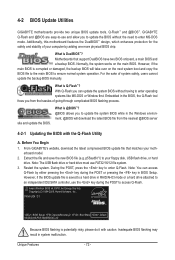
...Q-Flash Utility A. Before You Begin 1. Restart the system. However, if the BIOS update file is Q-Flash™? P55A-UD6 D1 . . . . : BIOS Setup : XpressRecovery2 : Boot Menu : Qflash 09/23/2009-P55-7A89RG0XC-00 Because BIOS flashing is @BIOS™? @BIOS allows you from the nearest @BIOS server 4-2-1 Updating the ...the next system boot and copy the BIOS file to the main BIOS to enter MS-DOS mode. p55aud6.f1) to enter Q-Flash. From GIGABYTE's website, download the latest compressed BIOS update file that support DualBIOS have two BIOS onboard, a main BIOS and a backup BIOS. Note:...
...Q-Flash Utility A. Before You Begin 1. Restart the system. However, if the BIOS update file is Q-Flash™? P55A-UD6 D1 . . . . : BIOS Setup : XpressRecovery2 : Boot Menu : Qflash 09/23/2009-P55-7A89RG0XC-00 Because BIOS flashing is @BIOS™? @BIOS allows you from the nearest @BIOS server 4-2-1 Updating the ...the next system boot and copy the BIOS file to the main BIOS to enter MS-DOS mode. p55aud6.f1) to enter Q-Flash. From GIGABYTE's website, download the latest compressed BIOS update file that support DualBIOS have two BIOS onboard, a main BIOS and a backup BIOS. Note:...

Manual
Page 87
...; At least two SATA hard drives (to available SATA port on this motherboard, the SATA2_0, SATA2_1, SATA2_2, SATA2_3, SATA2_4 and SATA2_5 ports are supported by P55 Chipset.) Then connect the power connector from your computer Attach one end of the SATA signal cable to the rear of the SATA hard drive..., it is more than one hard drive. • An empty formatted floppy disk. • Windows Vista/XP setup disk. • Motherboard driver disk. 5-1-1 Configuring Intel P55 SATA Controllers A.
...; At least two SATA hard drives (to available SATA port on this motherboard, the SATA2_0, SATA2_1, SATA2_2, SATA2_3, SATA2_4 and SATA2_5 ports are supported by P55 Chipset.) Then connect the power connector from your computer Attach one end of the SATA signal cable to the rear of the SATA hard drive..., it is more than one hard drive. • An empty formatted floppy disk. • Windows Vista/XP setup disk. • Motherboard driver disk. 5-1-1 Configuring Intel P55 SATA Controllers A.
Manual
Page 89
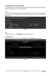
... Create RAID Volume in RAID BIOS Enter the RAID BIOS setup utility to enter Configuration Utility" (Figure 2). Figure 2 Step 2: After you want to enter the P55 RAID Configuration Utility. Create RAID Volume If you press + , the MAIN MENU screen will appear (Figure 3). Exit 3. Skip this step and proceed with the installation...
... Create RAID Volume in RAID BIOS Enter the RAID BIOS setup utility to enter Configuration Utility" (Figure 2). Figure 2 Step 2: After you want to enter the P55 RAID Configuration Utility. Create RAID Volume If you press + , the MAIN MENU screen will appear (Figure 3). Exit 3. Skip this step and proceed with the installation...
Manual
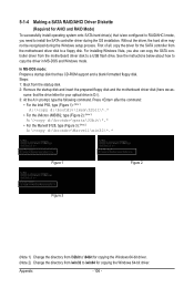
Page 106
... the SATA controller from the motherboard driver disk to \64bit for copying the Windows 64-bit driver. Press after the command: • For the Intel P55, type (Figure 1): (Note 1) A:\>copy d:\bootdrv\imsm\32bit\*.* • For the JMicron JMB362, type (Figure 2): (Note 1) A:\>copy d:\bootdrv\gsata\32bit\*.* • For the Marvell 9128, type...
... the SATA controller from the motherboard driver disk to \64bit for copying the Windows 64-bit driver. Press after the command: • For the Intel P55, type (Figure 1): (Note 1) A:\>copy d:\bootdrv\imsm\32bit\*.* • For the JMicron JMB362, type (Figure 2): (Note 1) A:\>copy d:\bootdrv\gsata\32bit\*.* • For the Marvell 9128, type...

Manual
Page 107
... driver by pressing the corresponding letter from the menu in the BootDrv folder (Figure 4). tem. • For the JMicron JMB362, select 3) GIGABYTE GSATA driver for 32bit system for Windows XP operating sys- Your system will open similar to the floppy disk. A Command Prompt window will then... and insert the motherboard driver disk. 2: From your optical drive folder, double click the Menu.exe file in Figure 5, • For the Intel P55, select 1) Intel Matrix Storage driver for 32bit system for Windows 32-bit op- Figure 4 Figure 5 - 107 - Depending on the operating system ...
... driver by pressing the corresponding letter from the menu in the BootDrv folder (Figure 4). tem. • For the JMicron JMB362, select 3) GIGABYTE GSATA driver for 32bit system for Windows XP operating sys- Your system will open similar to the floppy disk. A Command Prompt window will then... and insert the motherboard driver disk. 2: From your optical drive folder, double click the Menu.exe file in Figure 5, • For the Intel P55, select 1) Intel Matrix Storage driver for 32bit system for Windows 32-bit op- Figure 4 Figure 5 - 107 - Depending on the operating system ...

Manual
Page 108
A. Figure 1 Step 2: For the Intel P55: Insert the floppy disk containing the SATA RAID/AHCI driver and press . Select the SCSI Adapter you want from the Windows XP setup disk and ...
A. Figure 1 Step 2: For the Intel P55: Insert the floppy disk containing the SATA RAID/AHCI driver and press . Select the SCSI Adapter you want from the Windows XP setup disk and ...

Manual
Page 110
For the Intel P55: Step 1: Restart your system to \iMSM\32Bit (for Windows Vista 32-bit) or \iMSM\64Bit (for Windows Vista 64-bit). Method B: Insert the USB flash ...
For the Intel P55: Step 1: Restart your system to \iMSM\32Bit (for Windows Vista 32-bit) or \iMSM\64Bit (for Windows Vista 64-bit). Method B: Insert the USB flash ...

Manual
Page 114
...-22LS Serial # 3JT354CP WD-WMAM9W736333 Size 111.7GB 111.7GB Type/Status(Vol ID) Member Disk (0) Member Disk (0) Volumes with a new one .) For the Intel P55: Turn off your computer. • Enabling Automatic Rebuild Step 1: When the message "Press to enter Configuration Utility" appears, press + to Non-RAID 4. The following screen...
...-22LS Serial # 3JT354CP WD-WMAM9W736333 Size 111.7GB 111.7GB Type/Status(Vol ID) Member Disk (0) Member Disk (0) Volumes with a new one .) For the Intel P55: Turn off your computer. • Enabling Automatic Rebuild Step 1: When the message "Press to enter Configuration Utility" appears, press + to Non-RAID 4. The following screen...

Manual
Page 116
... drive detects a virus, you can restore the recovery drive data to Master. RecSoevlercyt:aCRoepcioesvedraytavboelutwmeeetnoadmo tahseteorpaenrdataiorne.covery disk. For example, in the MAIN MENU of the P55 RAID Configuration Utility. Intel(R) Matrix Storage Manager option ROM v8.9.0.1023 PCH-D wRAID5 Copyright(C) 2003-09 Intel Corporation. RAID1: Mirrors data (redundancy). Step 3: To check...
... drive detects a virus, you can restore the recovery drive data to Master. RecSoevlercyt:aCRoepcioesvedraytavboelutwmeeetnoadmo tahseteorpaenrdataiorne.covery disk. For example, in the MAIN MENU of the P55 RAID Configuration Utility. Intel(R) Matrix Storage Manager option ROM v8.9.0.1023 PCH-D wRAID5 Copyright(C) 2003-09 Intel Corporation. RAID1: Mirrors data (redundancy). Step 3: To check...
