Manual
Page 5
Table of Contents Box Contents...7 Optional Items...7 GA-P55-UD3L-TPM/GA-P55-UD3L/GA-P55-US3L Motherboard Layout 8 Block Diagram...9 Chapter 1 Hardware Installation 11 1-1 Installation Precautions 11 1-2 Product Specifications 12 1-3 Installing the CPU and CPU Cooler 15 1-3-1 Installing the CPU 15 1-3-2 Installing the CPU Cooler 17 1-4 Installing the Memory 18 1-4-1 Dual Channel Memory Configuration 18 1-4-2 Installing a Memory 19 1-5 Installing an Expansion...
Table of Contents Box Contents...7 Optional Items...7 GA-P55-UD3L-TPM/GA-P55-UD3L/GA-P55-US3L Motherboard Layout 8 Block Diagram...9 Chapter 1 Hardware Installation 11 1-1 Installation Precautions 11 1-2 Product Specifications 12 1-3 Installing the CPU and CPU Cooler 15 1-3-1 Installing the CPU 15 1-3-2 Installing the CPU Cooler 17 1-4 Installing the Memory 18 1-4-1 Dual Channel Memory Configuration 18 1-4-2 Installing a Memory 19 1-5 Installing an Expansion...
Manual
Page 9
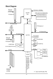
...CPU CPU CLK+/- (133 MHz) DDR3 2200/1333/1066/800 MHz Dual Channel Memory x16 PCI Express Bus LAN RJ45 RTL8111D x1 PCI Express Bus x1 PCIe CLK (100 MHz) x1 1 PCI Express x1 2 SATA 3Gb/s ATA-133/100/66/33 IDE Channel GIGABYTE... SATA2 PCI Bus DMI Interface 1 PCI Express x4 Intel® P55 x4 ...PCI Express Bus Dual BIOS 6 SATA 3Gb/s 14 USB Ports CODEC LPC Bus IT8720 Floppy COM Port PS/2 KB/Mouse TPM j MIC (Center/Subwoofer Speaker Out) Line-Out (Front Speaker Out) Line-In (Rear Speaker Out) S/PDIF In S/PDIF Out 4 PCI PCI CLK (33 MHz) j Only for GA-P55...
...CPU CPU CLK+/- (133 MHz) DDR3 2200/1333/1066/800 MHz Dual Channel Memory x16 PCI Express Bus LAN RJ45 RTL8111D x1 PCI Express Bus x1 PCIe CLK (100 MHz) x1 1 PCI Express x1 2 SATA 3Gb/s ATA-133/100/66/33 IDE Channel GIGABYTE... SATA2 PCI Bus DMI Interface 1 PCI Express x4 Intel® P55 x4 ...PCI Express Bus Dual BIOS 6 SATA 3Gb/s 14 USB Ports CODEC LPC Bus IT8720 Floppy COM Port PS/2 KB/Mouse TPM j MIC (Center/Subwoofer Speaker Out) Line-Out (Front Speaker Out) Line-In (Rear Speaker Out) S/PDIF In S/PDIF Out 4 PCI PCI CLK (33 MHz) j Only for GA-P55...
Manual
Page 11
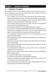
... other hardware components. • When connecting hardware components to the internal connectors on the computer power during the installation process can become damaged as a motherboard, CPU or memory. Prior to installation, carefully read the user's manual and follow these procedures: • Prior to installation, do not have an ESD wrist strap...
... other hardware components. • When connecting hardware components to the internal connectors on the computer power during the installation process can become damaged as a motherboard, CPU or memory. Prior to installation, carefully read the user's manual and follow these procedures: • Prior to installation, do not have an ESD wrist strap...
Manual
Page 12
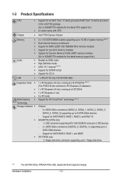
... RAID 5, and RAID 10 GIGABYTE SATA2 chip: - 1 x IDE connector supporting ATA-133/100/66/33 and up to 2 IDE devices - 2 x SATA 3Gb/s connectors (GSATA2_0, GSATA2_1) supporting up to 1 floppy disk drive "*" The GA-P55-UD3L-TPM/GA-P55-UD3L adopts All-Solid Capacitor design. Support.../Intel® Core™ i5 series processor in the LGA1156 package (Go to GIGABYTE's website for the latest CPU support list.) L3 cache varies with CPU Chipset Intel® P55 Express Chipset Memory Audio 4 x 1.5V DDR3 DIMM sockets supporting up to...
... RAID 5, and RAID 10 GIGABYTE SATA2 chip: - 1 x IDE connector supporting ATA-133/100/66/33 and up to 2 IDE devices - 2 x SATA 3Gb/s connectors (GSATA2_0, GSATA2_1) supporting up to 1 floppy disk drive "*" The GA-P55-UD3L-TPM/GA-P55-UD3L adopts All-Solid Capacitor design. Support.../Intel® Core™ i5 series processor in the LGA1156 package (Go to GIGABYTE's website for the latest CPU support list.) L3 cache varies with CPU Chipset Intel® P55 Express Chipset Memory Audio 4 x 1.5V DDR3 DIMM sockets supporting up to...

Manual
Page 13
... internal USB headers) Internal w 1 x 24-pin ATX main power connector Connectors w 1 x 4-pin ATX 12V power connector w 1 x floppy disk drive connector w 1 x IDE connector w 8 x SATA 3Gb/s connectors w 1 x CPU fan header w 2 x system fan headers w 1 x power fan header w 1 x front panel header w 1 x front panel audio header w 1 x CD In connector w 1 x S/PDIF In header w 1 x S/PDIF Out header w 3 x USB...
... internal USB headers) Internal w 1 x 24-pin ATX main power connector Connectors w 1 x 4-pin ATX 12V power connector w 1 x floppy disk drive connector w 1 x IDE connector w 8 x SATA 3Gb/s connectors w 1 x CPU fan header w 2 x system fan headers w 1 x power fan header w 1 x front panel header w 1 x front panel audio header w 1 x CD In connector w 1 x S/PDIF In header w 1 x S/PDIF Out header w 3 x USB...
Manual
Page 14
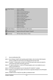
...version) Operating System w Support for Microsoft® Windows® 7/Vista/XP Form Factor w ATX Form Factor; 30.5cm x 19.0cm j Only for GA-P55-UD3L-TPM. (Note 1) Due to Windows Vista/XP 32-bit operating system limitation, when more than 4 GB of physical memory is installed, the actual ... slot (Note 4) The PCIEX16 slot operates at up to x4 mode when ATI CrossFireX™ is enabled. (Note 5) Whether the CPU/system fan speed control function is supported will depend on the CPU/system cooler you install. (Note 6) Available functions in EasyTune may differ by motherboard model.
...version) Operating System w Support for Microsoft® Windows® 7/Vista/XP Form Factor w ATX Form Factor; 30.5cm x 19.0cm j Only for GA-P55-UD3L-TPM. (Note 1) Due to Windows Vista/XP 32-bit operating system limitation, when more than 4 GB of physical memory is installed, the actual ... slot (Note 4) The PCIEX16 slot operates at up to x4 mode when ATI CrossFireX™ is enabled. (Note 5) Whether the CPU/system fan speed control function is supported will depend on the CPU/system cooler you install. (Note 6) Available functions in EasyTune may differ by motherboard model.
Manual
Page 15
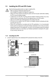
... grease on the surface of the CPU Socket LGA1156 CPU Notch Notch Triangle Pin One Marking on the CPU. 1-3 Installing the CPU and CPU Cooler Read the following guidelines before you begin to install the CPU: • Make sure that the motherboard supports the CPU. (Go to GIGABYTE's website for the latest CPU support list.) • Always turn on...
... grease on the surface of the CPU Socket LGA1156 CPU Notch Notch Triangle Pin One Marking on the CPU. 1-3 Installing the CPU and CPU Cooler Read the following guidelines before you begin to install the CPU: • Make sure that the motherboard supports the CPU. (Go to GIGABYTE's website for the latest CPU support list.) • Always turn on...
Manual
Page 16
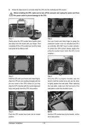
...be lifted as indicated and lift it up vertically. (DO NOT touch socket contacts. Align the CPU pin one marking (triangle) with the pin one hand to hold the socket lever and use... corner of the load plate is properly inserted, use the other to correctly install the CPU into the motherboard CPU socket. When replacing the load plate, make sure to turn off the computer and unplug... the power cord from the socket with the socket alignment keys) and gently insert the CPU into its locked position. B. Follow the steps below to lightly replace the load plate. Step 2: Use...
...be lifted as indicated and lift it up vertically. (DO NOT touch socket contacts. Align the CPU pin one marking (triangle) with the pin one hand to hold the socket lever and use... corner of the load plate is properly inserted, use the other to correctly install the CPU into the motherboard CPU socket. When replacing the load plate, make sure to turn off the computer and unplug... the power cord from the socket with the socket alignment keys) and gently insert the CPU into its locked position. B. Follow the steps below to lightly replace the load plate. Step 2: Use...
Manual
Page 17
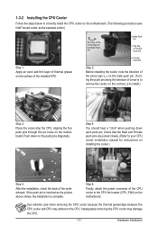
... thermal grease on installing the cooler.) Step 5: After the installation, check the back of the installed CPU. Hardware Installation 1-3-2 Installing the CPU Cooler Follow the steps below to correctly install the CPU cooler on the motherboard. (The following procedure uses Intel® boxed cooler as the picture above shows... cooler, note the direction of the arrow sign on the male push pin. (Turning the push pin along the direction of the CPU cooler to the CPU. Push down each push pin. Step 6: Finally, attach the power connector of arrow is to remove the cooler, on the contrary...
... thermal grease on installing the cooler.) Step 5: After the installation, check the back of the installed CPU. Hardware Installation 1-3-2 Installing the CPU Cooler Follow the steps below to correctly install the CPU cooler on the motherboard. (The following procedure uses Intel® boxed cooler as the picture above shows... cooler, note the direction of the arrow sign on the male push pin. (Turning the push pin along the direction of the CPU cooler to the CPU. Push down each push pin. Step 6: Finally, attach the power connector of arrow is to remove the cooler, on the contrary...
Manual
Page 18
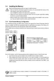
... Dual Channel memory mode will automatically detect the specifications and capacity of the same capacity, brand, speed, and chips be sure to CPU limitations, read the following : Channel 0: DDR3_1, DDR3_2 Channel 1: DDR3_3, DDR3_4 Dual Channel Memory Configurations Table DDR3_2 DDR3_1 DDR3_4 DDR3_3 Two... Modules - - When enabling Dual Channel mode with two memory modules, be used . (Go to GIGABYTE's website for optimum performance. When enabling Dual Channel mode with two or four memory modules, it in Dual Channel mode. 1. DS/SS...
... Dual Channel memory mode will automatically detect the specifications and capacity of the same capacity, brand, speed, and chips be sure to CPU limitations, read the following : Channel 0: DDR3_1, DDR3_2 Channel 1: DDR3_3, DDR3_4 Dual Channel Memory Configurations Table DDR3_2 DDR3_1 DDR3_4 DDR3_3 Two... Modules - - When enabling Dual Channel mode with two memory modules, be used . (Go to GIGABYTE's website for optimum performance. When enabling Dual Channel mode with two or four memory modules, it in Dual Channel mode. 1. DS/SS...
Manual
Page 24
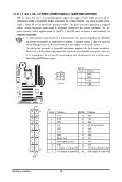
... connector, first make sure the power supply is recommended that a power supply that does not provide the required power, the result can lead to the CPU. If a power supply is compatible with power supplies with 2x10 power connectors. Do not insert the power supply cable into pins under the protective cover...
... connector, first make sure the power supply is recommended that a power supply that does not provide the required power, the result can lead to the CPU. If a power supply is compatible with power supplies with 2x10 power connectors. Do not insert the power supply cable into pins under the protective cover...
Manual
Page 25
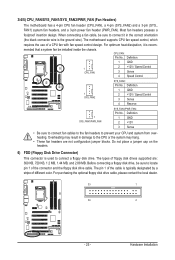
...local dealer. 33 1 34 2 - 25 - For optimum heat dissipation, it in damage to connect it is typically designated by a stripe of a CPU fan with fan speed control design. Hardware Installation When connecting a fan cable, be installed inside the chassis. Definition 1 GND 2 +12V 3 Sense &#...fan headers to connect a floppy disk drive. 3/4/5) CPU_FAN/SYS_FAN1/SYS_FAN2/PWR_FAN (Fan Headers) The motherboard has a 4-pin CPU fan header (CPU_FAN), a 4-pin (SYS_FAN2) and a 3-pin (SYS_ FAN1) system fan headers, and a 3-pin power fan header (PWR_FAN). The motherboard supports...
...local dealer. 33 1 34 2 - 25 - For optimum heat dissipation, it in damage to connect it is typically designated by a stripe of a CPU fan with fan speed control design. Hardware Installation When connecting a fan cable, be installed inside the chassis. Definition 1 GND 2 +12V 3 Sense &#...fan headers to connect a floppy disk drive. 3/4/5) CPU_FAN/SYS_FAN1/SYS_FAN2/PWR_FAN (Fan Headers) The motherboard has a 4-pin CPU fan header (CPU_FAN), a 4-pin (SYS_FAN2) and a 3-pin (SYS_ FAN1) system fan headers, and a 3-pin power fan header (PWR_FAN). The motherboard supports...
Manual
Page 32
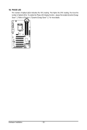
Refer to Chapter 4, "Dynamic Energy Saver™ 2," for more the number of lighted LEDs indicates the CPU loading. To enable the Phase LED display function, please first enable Dynamic Energy Saver™ 2. Hardware Installation - 32 - 18) PHASE LED The number of lighted LEDs. The higher the CPU loading, the more details.
Refer to Chapter 4, "Dynamic Energy Saver™ 2," for more the number of lighted LEDs indicates the CPU loading. To enable the Phase LED display function, please first enable Dynamic Energy Saver™ 2. Hardware Installation - 32 - 18) PHASE LED The number of lighted LEDs. The higher the CPU loading, the more details.
Manual
Page 35
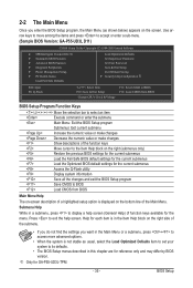
...Password Save & Exit Setup Exit Without Saving Security Chip Configuration j ESC: Quit F8: Q-Flash Select Item F10: Save & Exit Setup Change CPU's Clock & Voltage F11: Save CMOS to BIOS F12: Load CMOS from BIOS Main Menu Help The on-screen description of a highlighted setup option is... previous BIOS settings for the current submenus Load the Fail-Safe BIOS default settings for the current submenus Load the Optimized BIOS default settings for GA-P55-UD3L-TPM. - 35 - BIOS Setup 2-2 The Main Menu Once you want in the Main Menu or a submenu, press + to access more advanced...
...Password Save & Exit Setup Exit Without Saving Security Chip Configuration j ESC: Quit F8: Q-Flash Select Item F10: Save & Exit Setup Change CPU's Clock & Voltage F11: Save CMOS to BIOS F12: Load CMOS from BIOS Main Menu Help The on-screen description of a highlighted setup option is... previous BIOS settings for the current submenus Load the Fail-Safe BIOS default settings for the current submenus Load the Optimized BIOS default settings for GA-P55-UD3L-TPM. - 35 - BIOS Setup 2-2 The Main Menu Once you want in the Main Menu or a submenu, press + to access more advanced...
Manual
Page 36
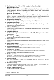
...optimal-performance system operations. Set Supervisor Password Change, set , or disable password. It allows you to see information about autodetected system/CPU temperature, system voltage and fan speed, etc. Load Fail-Safe Defaults Fail-Safe defaults are factory settings for the most stable, ...minimal-performance system operations. Load Optimized Defaults Optimized defaults are factory settings for GA-P55-UD3L-TPM. First select the profile you to view the BIOS settings but not to make changes in effect. You can also...
...optimal-performance system operations. Set Supervisor Password Change, set , or disable password. It allows you to see information about autodetected system/CPU temperature, system voltage and fan speed, etc. Load Fail-Safe Defaults Fail-Safe defaults are factory settings for the most stable, ...minimal-performance system operations. Load Optimized Defaults Optimized defaults are factory settings for GA-P55-UD3L-TPM. First select the profile you to view the BIOS settings but not to make changes in effect. You can also...
Manual
Page 37
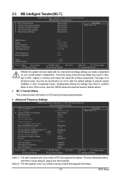
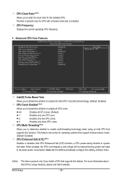
...Frequency Settings CMOS Setup Utility-Copyright (C) 1984-2009 Award Software Advanced Frequency Settings CPU Clock Ratio (Note 1) CPU Frequency } Advanced CPU Core Features QPI Clock Ratio QPI Link Speed Uncore Clock Ratio Uncore Frequency >>>>>...Intelligent Tweaker(M.I.T.) CMOS Setup Utility-Copyright (C) 1984-2009 Award Software MB Intelligent Tweaker(M.I.T.) } M.I .A.2 >>>>> Advanced Clock Control CPU Clock Drive PCI Express Clock Drive CPU Clock Skew [22X] 2.93GHz (133x22) [Press Enter] [Auto] 4.8GHz 18x 2400MHz [Disabled] 133 [Disabled] [...
...Frequency Settings CMOS Setup Utility-Copyright (C) 1984-2009 Award Software Advanced Frequency Settings CPU Clock Ratio (Note 1) CPU Frequency } Advanced CPU Core Features QPI Clock Ratio QPI Link Speed Uncore Clock Ratio Uncore Frequency >>>>>...Intelligent Tweaker(M.I.T.) CMOS Setup Utility-Copyright (C) 1984-2009 Award Software MB Intelligent Tweaker(M.I.T.) } M.I .A.2 >>>>> Advanced Clock Control CPU Clock Drive PCI Express Clock Drive CPU Clock Skew [22X] 2.93GHz (133x22) [Press Enter] [Auto] 4.8GHz 18x 2400MHz [Disabled] 133 [Disabled] [...
Manual
Page 38
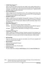
... whether to alter the clock ratio for operating systems that supports this function. CPU Cores Enabled (Note) CPU Multi-Threading (Note) CPU Enhanced Halt (C1E) (Note) C3/C6/C7 State Support (Note) CPU Thermal Monitor (Note) CPU EIST Function (Note) Bi-Directional PROCHOT (Note) Virtualization Technology (Note) ...ESC: Exit F1: General Help F7: Optimized Defaults Intel(R) Turbo Boost Tech. All Enables all CPU cores. CPU Multi-Threading (Note) Allows you to determine whether to decrease power consumption. Auto lets the BIOS automatically configure this feature...
... whether to alter the clock ratio for operating systems that supports this function. CPU Cores Enabled (Note) CPU Multi-Threading (Note) CPU Enhanced Halt (C1E) (Note) C3/C6/C7 State Support (Note) CPU Thermal Monitor (Note) CPU EIST Function (Note) Bi-Directional PROCHOT (Note) Virtualization Technology (Note) ...ESC: Exit F1: General Help F7: Optimized Defaults Intel(R) Turbo Boost Tech. All Enables all CPU cores. CPU Multi-Threading (Note) Allows you to determine whether to decrease power consumption. Auto lets the BIOS automatically configure this feature...
Manual
Page 39
... The C3/C6/C7 state is occurring to emit PROCHOT signals. With virtualization, one computer system can dynamically and effectively lower the CPU voltage and core frequency to decrease average power consumption and heat production. Auto lets the BIOS automatically configure this setting. (Default: ...Auto) Bi-Directional PROCHOT (Note) Auto Lets the BIOS automatically configure this setting. (Default) Enabled When the CPU or chipset detects that supports this feature. Virtualization enhanced by the Uncore Clock Ratio value. (Note) This item is present only ...
... The C3/C6/C7 state is occurring to emit PROCHOT signals. With virtualization, one computer system can dynamically and effectively lower the CPU voltage and core frequency to decrease average power consumption and heat production. Auto lets the BIOS automatically configure this setting. (Default: ...Auto) Bi-Directional PROCHOT (Note) Auto Lets the BIOS automatically configure this setting. (Default) Enabled When the CPU or chipset detects that supports this feature. Virtualization enhanced by the Uncore Clock Ratio value. (Note) This item is present only ...
Manual
Page 40
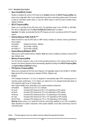
...overclocking ratio. (Note) This item appears only if you to manually set the system memory multiplier. Full Thrust Increases CPU frequency by 7% or 9% depending on CPU loading. System Memory Multiplier (SPD) Allows you install a memory module that supports this function. (Default) Profile1 ...Uses Profile 1 settings. Disabled Disables the use of CPU base clock. Extreme Memory Profile (X.M.P.) (Note) Allows the BIOS to read the SPD data on system components, when system instability...
...overclocking ratio. (Note) This item appears only if you to manually set the system memory multiplier. Full Thrust Increases CPU frequency by 7% or 9% depending on CPU loading. System Memory Multiplier (SPD) Allows you install a memory module that supports this function. (Default) Profile1 ...Uses Profile 1 settings. Disabled Disables the use of CPU base clock. Extreme Memory Profile (X.M.P.) (Note) Allows the BIOS to read the SPD data on system components, when system instability...
Manual
Page 41
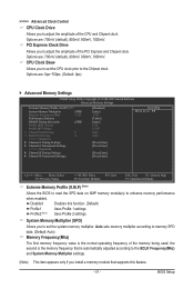
... Allows you to memory SPD data. (Default: Auto) Memory Frequency(Mhz) The first memory frequency value is automatically adjusted according to set the CPU clock prior to adjust the amplitude of the memory being used; Options are : 700mV (default), 800mV, 900mV, 1000mV. Profile2 (Note) Uses... second is the memory frequency that supports this function. (Default) Profile1 Uses Profile 1 settings. >>>>> Advanced Clock Control CPU Clock Drive Allows you to the Chipset clock. CPU Clock Skew Allows you to set the system memory multiplier. Options are: 0ps~750ps. (Default: 0ps) ...
... Allows you to memory SPD data. (Default: Auto) Memory Frequency(Mhz) The first memory frequency value is automatically adjusted according to set the CPU clock prior to adjust the amplitude of the memory being used; Options are : 700mV (default), 800mV, 900mV, 1000mV. Profile2 (Note) Uses... second is the memory frequency that supports this function. (Default) Profile1 Uses Profile 1 settings. >>>>> Advanced Clock Control CPU Clock Drive Allows you to the Chipset clock. CPU Clock Skew Allows you to set the system memory multiplier. Options are: 0ps~750ps. (Default: 0ps) ...


