
Manual
Page 4
Table of Contents Box Contents ...6 OptionalItems ...6 GA-P35-DS4 Motherboard Layout 7 Block Diagram ...8 Chapter 1 Hardware Installation 9 1-1 Installation Precautions 9 1-2 Product Specifications 10 1-3 Installing the CPU and CPU Cooler 13 1-3-1 Installing the CPU 13 1-3-2 Installing the CPU Cooler 15 1-4 Installing the Memory 16 1-4-1 Dual Channel Memory Configuration 16 1-4-2 Installing a Memory 17 1-5 Installing an Expansion Card 18 1-6 Installing the SATA Bracket...
Table of Contents Box Contents ...6 OptionalItems ...6 GA-P35-DS4 Motherboard Layout 7 Block Diagram ...8 Chapter 1 Hardware Installation 9 1-1 Installation Precautions 9 1-2 Product Specifications 10 1-3 Installing the CPU and CPU Cooler 13 1-3-1 Installing the CPU 13 1-3-2 Installing the CPU Cooler 15 1-4 Installing the Memory 16 1-4-1 Dual Channel Memory Configuration 16 1-4-2 Installing a Memory 17 1-5 Installing an Expansion Card 18 1-6 Installing the SATA Bracket...
Manual
Page 6
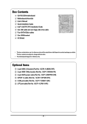
The box contents are for reference only. Box Contents GA-P35-DS4 motherboard Motherboard driver disk User's Manual Quick Installation Guide Intel® LGA775 CPU Installation Guide One IDE cable and one floppy disk drive cable Four SATA 3Gb/s cables One SATA bracket I/O Shield • The box contents above are ...
The box contents are for reference only. Box Contents GA-P35-DS4 motherboard Motherboard driver disk User's Manual Quick Installation Guide Intel® LGA775 CPU Installation Guide One IDE cable and one floppy disk drive cable Four SATA 3Gb/s cables One SATA bracket I/O Shield • The box contents above are ...

Manual
Page 8
... x1 PCI Express Bus 2 SATA 3Gb/s ATA-133/100/66/ 33 IDE Channel GIGABYTE SATA2 PCI Bus TSB43AB23 3 IEEE 1394a LGA775 Processor CPU CLK+/- (400 (O.C.)/333/ 266/200 MHz) Host Interface DDR2 1200 (O.C.)/1066/ 800/667 MHz Intel® P35 Dual Channel Memory MCH CLK (333/266/200 MHz) Intel® ICH9R CODEC...
... x1 PCI Express Bus 2 SATA 3Gb/s ATA-133/100/66/ 33 IDE Channel GIGABYTE SATA2 PCI Bus TSB43AB23 3 IEEE 1394a LGA775 Processor CPU CLK+/- (400 (O.C.)/333/ 266/200 MHz) Host Interface DDR2 1200 (O.C.)/1066/ 800/667 MHz Intel® P35 Dual Channel Memory MCH CLK (333/266/200 MHz) Intel® ICH9R CODEC...
Manual
Page 9
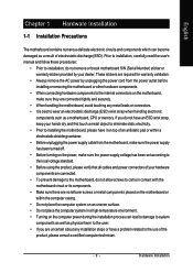
...; Do not place the computer system in a high-temperature environment. • Turning on the computer power during the installation process can become damaged as a motherboard, CPU or memory. These stickers are required for warranty validation. • Always remove the AC power by your hardware components are connected tightly and securely. •...
...; Do not place the computer system in a high-temperature environment. • Turning on the computer power during the installation process can become damaged as a motherboard, CPU or memory. These stickers are required for warranty validation. • Always remove the AC power by your hardware components are connected tightly and securely. •...
Manual
Page 10
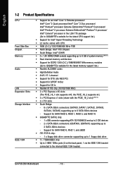
...4 processor Extreme Edition/Intel® Pentium® 4 processor/ Intel® Celeron® processor in the LGA 775 package (Go to GIGABYTE's website for the latest CPU support list.) Š Support for Intel® Hyper-Threading Technology Š L2 cache varies with the PCIE_16_2 slot) (Note 2) &#... P35 Chipset Š South Bridge: Intel® ICH9R Š 4 x 1.8V DDR2 DIMM sockets supporting up to 8 GB of system memory (Note 1) Š Dual channel memory architecture Š Support for DDR2 1200 (O.C.)/1066/800/667 MHz memory modules (Go to the internal IEEE 1394 header) GA-P35-DS4 ...
...4 processor Extreme Edition/Intel® Pentium® 4 processor/ Intel® Celeron® processor in the LGA 775 package (Go to GIGABYTE's website for the latest CPU support list.) Š Support for Intel® Hyper-Threading Technology Š L2 cache varies with the PCIE_16_2 slot) (Note 2) &#... P35 Chipset Š South Bridge: Intel® ICH9R Š 4 x 1.8V DDR2 DIMM sockets supporting up to 8 GB of system memory (Note 1) Š Dual channel memory architecture Š Support for DDR2 1200 (O.C.)/1066/800/667 MHz memory modules (Go to the internal IEEE 1394 header) GA-P35-DS4 ...

Manual
Page 11
...Š 1 x 4-pin PCIe 12V power connector Š 1 x floppy disk drive connector Š 1 x IDE connector Š 8 x SATA 3Gb/s connectors Š 1 x CPU fan header Š 2 x system fan headers Š 1 x power fan header Š 1 x North Bridge fan header Š 1 x front panel header Š 1 ...138; iTE IT8718 chip Hardware Monitor Š System voltage detection Š CPU/System temperature detection Š CPU/System/Power fan speed detection Š CPU overheating warning Š CPU/System/Power fan fail warning Š CPU fan speed control - 11 - Hardware Installation
...Š 1 x 4-pin PCIe 12V power connector Š 1 x floppy disk drive connector Š 1 x IDE connector Š 8 x SATA 3Gb/s connectors Š 1 x CPU fan header Š 2 x system fan headers Š 1 x power fan header Š 1 x North Bridge fan header Š 1 x front panel header Š 1 ...138; iTE IT8718 chip Hardware Monitor Š System voltage detection Š CPU/System temperature detection Š CPU/System/Power fan speed detection Š CPU overheating warning Š CPU/System/Power fan fail warning Š CPU fan speed control - 11 - Hardware Installation

Manual
Page 12
... you to: - Adjust DDR2 frequency - Increase DDR2 voltage by motherboard model. (Note 4) The adjustable CPU voltage range depends on the CPU being used. (Note 5) Due to 150 MHz with 1 MHz increment - GA-P35-DS4 Motherboard - 12 - English BIOS Unique Features Bundled Software Overclocking Operating System Form Factor Š 2 x... unavailable. (Note 3) Available functions in Easytune may differ by 0.05V to 1.55V with 0.05V increment - Adjust CPU host frequency from 90 MHz to chipset limitation, Intel ICH9R RAID driver does not support Windows 2000 operating system. Increase...
... you to: - Adjust DDR2 frequency - Increase DDR2 voltage by motherboard model. (Note 4) The adjustable CPU voltage range depends on the CPU being used. (Note 5) Due to 150 MHz with 1 MHz increment - GA-P35-DS4 Motherboard - 12 - English BIOS Unique Features Bundled Software Overclocking Operating System Form Factor Š 2 x... unavailable. (Note 3) Available functions in Easytune may differ by 0.05V to 1.55V with 0.05V increment - Adjust CPU host frequency from 90 MHz to chipset limitation, Intel ICH9R RAID driver does not support Windows 2000 operating system. Increase...
Manual
Page 13
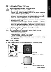
... Key Pin One Corner of the CPU. • Do not turn on the computer if the CPU cooler is optimized for HT Technology • A BIOS that the motherboard supports the CPU. (Go to GIGABYTE's website for the latest CPU support list.) • Always turn off the computer and unplug the power ...cord from the power outlet before you begin to install the CPU: • Make sure that supports HT Technology and has ...
... Key Pin One Corner of the CPU. • Do not turn on the computer if the CPU cooler is optimized for HT Technology • A BIOS that the motherboard supports the CPU. (Go to GIGABYTE's website for the latest CPU support list.) • Always turn off the computer and unplug the power ...cord from the power outlet before you begin to install the CPU: • Make sure that supports HT Technology and has ...

Manual
Page 14
... power outlet to prevent damage to correctly install the CPU into the motherboard CPU socket. CPU Socket Lever Step 1: Completely raise the CPU socket lever. Follow the steps below to the CPU. GA-P35-DS4 Motherboard - 14 - Step 3: Lift the metal load plate on the CPU socket. Step 4: Hold the CPU with the socket alignment keys) and gently insert the...
... power outlet to prevent damage to correctly install the CPU into the motherboard CPU socket. CPU Socket Lever Step 1: Completely raise the CPU socket lever. Follow the steps below to the CPU. GA-P35-DS4 Motherboard - 14 - Step 3: Lift the metal load plate on the CPU socket. Step 4: Hold the CPU with the socket alignment keys) and gently insert the...

Manual
Page 15
... above, the installation is complete. Check that the Male and Female push pins are joined closely. (Refer to install.) Step 3: Place the cooler atop the CPU, aligning the four push pins through the pin holes on installing the cooler.) Step 5: After the installation, check the back of the installed... CPU. Step 6: Finally, attach the power connector of arrow is to remove the cooler, on the contrary, is inserted as the example cooler.) Step 1: Apply an...
... above, the installation is complete. Check that the Male and Female push pins are joined closely. (Refer to install.) Step 3: Place the cooler atop the CPU, aligning the four push pins through the pin holes on installing the cooler.) Step 5: After the installation, check the back of the installed... CPU. Step 6: Finally, attach the power connector of arrow is to remove the cooler, on the contrary, is inserted as the example cooler.) Step 1: Apply an...
Manual
Page 24
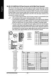
... main power connector on the motherboard. Do not insert the power supply cables into pins under the protective covers when using an Intel Extreme Edition CPU (130W). • To meet expansion requirements, it is used (400W or greater). If a power supply is recommended that a power supply that can withstand high.../Off) GND GND GND -5V +5V +5V +5V (Only for 2x12 pin ATX) GND (Only for 2x4 pin 12V) 7 +12V 8 +12V 12 24 1 13 ATX GA-P35-DS4 Motherboard ATX: Pin No. 1 2 3 4 5 6 7 8 9 10 11 12 Definition Pin No. 3.3V 13 3.3V 14 GND 15 +5V 16 GND 17 +5V 18 GND 19...
... main power connector on the motherboard. Do not insert the power supply cables into pins under the protective covers when using an Intel Extreme Edition CPU (130W). • To meet expansion requirements, it is used (400W or greater). If a power supply is recommended that a power supply that can withstand high.../Off) GND GND GND -5V +5V +5V +5V (Only for 2x12 pin ATX) GND (Only for 2x4 pin 12V) 7 +12V 8 +12V 12 24 1 13 ATX GA-P35-DS4 Motherboard ATX: Pin No. 1 2 3 4 5 6 7 8 9 10 11 12 Definition Pin No. 3.3V 13 3.3V 14 GND 15 +5V 16 GND 17 +5V 18 GND 19...

Manual
Page 26
...fan speed control design. Overheating may result in the correct orientation. English 4/5/6) CPU_FAN/SYS_FAN1/SYS_FAN2/PWR_FAN (Fan Headers) The motherboard has a 4-pin CPU fan header (CPU_FAN), a 3-pin (SYS_FAN1) and a 4-pin (SYS_FAN2) system fan headers, and a 3-pin power fan header (PWR_FAN).... sure to prevent your CPU, North Bridge and system from overheating. The motherboard supports CPU fan speed control, which requires the use of a CPU fan with color-coded power connector wires. The black connector wire is the ground wire. Pin No. GA-P35-DS4 Motherboard - 26 -
...fan speed control design. Overheating may result in the correct orientation. English 4/5/6) CPU_FAN/SYS_FAN1/SYS_FAN2/PWR_FAN (Fan Headers) The motherboard has a 4-pin CPU fan header (CPU_FAN), a 3-pin (SYS_FAN1) and a 4-pin (SYS_FAN2) system fan headers, and a 3-pin power fan header (PWR_FAN).... sure to prevent your CPU, North Bridge and system from overheating. The motherboard supports CPU fan speed control, which requires the use of a CPU fan with color-coded power connector wires. The black connector wire is the ground wire. Pin No. GA-P35-DS4 Motherboard - 26 -
Manual
Page 40
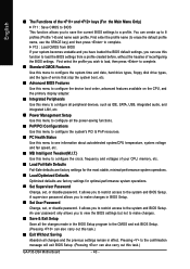
..., advanced features available on the CPU, and the primary display adapter. „ Integrated Peripherals Use this menu to configure all peripheral devices, such as IDE, SATA, USB, integrated audio, and integrated LAN, etc. „ Power Management Setup Use this task.) GA-P35-DS4 Motherboard - 40 - An user...this menu to configure the system's PCI & PnP resources. „ PC Health Status Use this menu to see information about autodetected system/CPU temperature, system voltage and fan speed, etc. „ MB Intelligent Tweaker(M.I.T.) Use this menu to configure the clock, frequency and voltages ...
..., advanced features available on the CPU, and the primary display adapter. „ Integrated Peripherals Use this menu to configure all peripheral devices, such as IDE, SATA, USB, integrated audio, and integrated LAN, etc. „ Power Management Setup Use this task.) GA-P35-DS4 Motherboard - 40 - An user...this menu to configure the system's PCI & PnP resources. „ PC Health Status Use this menu to see information about autodetected system/CPU temperature, system voltage and fan speed, etc. „ MB Intelligent Tweaker(M.I.T.) Use this menu to configure the clock, frequency and voltages ...

Manual
Page 43
...A password is required every time the system boots, or only when you install a CPU that support multi-processors mode. (Default: Enabled) (Note) This item is installed. (Default: Disabled) CPU Hyper-Threading (Note) Enables or disables Intel® Hyper-Threading Technology. Use the... Reporting Technology) capability of your system to report read/write errors of loading the operating system from the available devices. Capability CPU Hyper-Threading (Note) Limit CPUID Max. This feature allows your hard drive. English 2-4 Advanced BIOS Features CMOS Setup Utility-...
...A password is required every time the system boots, or only when you install a CPU that support multi-processors mode. (Default: Enabled) (Note) This item is installed. (Default: Disabled) CPU Hyper-Threading (Note) Enables or disables Intel® Hyper-Threading Technology. Use the... Reporting Technology) capability of your system to report read/write errors of loading the operating system from the available devices. Capability CPU Hyper-Threading (Note) Limit CPUID Max. This feature allows your hard drive. English 2-4 Advanced BIOS Features CMOS Setup Utility-...

Manual
Page 44
...Execute Disable Bit function. When enabled, the CPU core frequency and voltage will be reduced when the CPU is present only if you to determine whether to run multiple operating systems and applications in system halt state. GA-P35-DS4 Motherboard - 44 - Set this item to.... (Default: Enabled) CPU Thermal Monitor 2 (TM2) (Note) Enables or disables Intel® CPU Thermal Monitor (TM2) function, a CPU overheating protection function. When enabled, the CPU core frequency and voltage will be reduced during system halt state to display the GIGABYTE Logo at system startup....
...Execute Disable Bit function. When enabled, the CPU core frequency and voltage will be reduced when the CPU is present only if you to determine whether to run multiple operating systems and applications in system halt state. GA-P35-DS4 Motherboard - 44 - Set this item to.... (Default: Enabled) CPU Thermal Monitor 2 (TM2) (Note) Enables or disables Intel® CPU Thermal Monitor (TM2) function, a CPU overheating protection function. When enabled, the CPU core frequency and voltage will be reduced during system halt state to display the GIGABYTE Logo at system startup....

Manual
Page 51
... current system voltages. BIOS Setup Options are: Disabled (default), 60oC/140oF, 70oC/158oF, 80oC/ 176oF, 90oC/194oF. Current CPU/System Temperature Displays current CPU/system temperature. Check the fan condition or fan connection when this field will show "Yes", otherwise it will show "No"... Status Case Opened Vcore DDR18V +3.3V +12V Current System Temperature Current CPU Temperature Current CPU FAN Speed Current SYSTEM FAN1 Speed Current SYSTEM FAN2 Speed Current POWER FAN Speed CPU Warning Temperature CPU FAN Fail Warning SYSTEM FAN1 Fail Warning SYSTEM FAN2 Fail Warning POWER ...
... current system voltages. BIOS Setup Options are: Disabled (default), 60oC/140oF, 70oC/158oF, 80oC/ 176oF, 90oC/194oF. Current CPU/System Temperature Displays current CPU/system temperature. Check the fan condition or fan connection when this field will show "Yes", otherwise it will show "No"... Status Case Opened Vcore DDR18V +3.3V +12V Current System Temperature Current CPU Temperature Current CPU FAN Speed Current SYSTEM FAN1 Speed Current SYSTEM FAN2 Speed Current POWER FAN Speed CPU Warning Temperature CPU FAN Fail Warning SYSTEM FAN1 Fail Warning SYSTEM FAN2 Fail Warning POWER ...

Manual
Page 52
... the motherboard driver disk. Note: The Voltage mode can be set to the CPU temperature. GA-P35-DS4 Motherboard - 52 - This feature requires the installation of CPU fan installed and sets the optimal CPU fan control mode. (Default) Voltage Sets Voltage mode for a 3-pin CPU fan or a 4-pin CPU fan. Smart FAN Control Mode Specifies how to control...
... the motherboard driver disk. Note: The Voltage mode can be set to the CPU temperature. GA-P35-DS4 Motherboard - 52 - This feature requires the installation of CPU fan installed and sets the optimal CPU fan control mode. (Default) Voltage Sets Voltage mode for a 3-pin CPU fan or a 4-pin CPU fan. Smart FAN Control Mode Specifies how to control...

Manual
Page 53
...Tweaker(M.I.T.) CMOS Setup Utility-Copyright (C) 1984-2007 Award Software MB Intelligent Tweaker(M.I.T.) Robust Graphics Booster CPU Clock Ratio (Note) CPU Host Clock Control x CPU Host Frequency (Mhz) PCI Express Frequency (Mhz) C.I.A. 2 Performance Enhance System Memory Multiplier (SPD...DRAM DLL Settings ******** System Voltage Optimized System Voltage Control DDR2 OverVoltage Control PCI-E OverVoltage Control FSB OverVoltage Control (G)MCH OverVoltage Control CPU Voltage Control Normal CPU Vcore ******** [Auto] [16X] [Disabled] 200 Auto [Disabled] [Turbo] [Auto] 667 [Option 1] [Manual] [...
...Tweaker(M.I.T.) CMOS Setup Utility-Copyright (C) 1984-2007 Award Software MB Intelligent Tweaker(M.I.T.) Robust Graphics Booster CPU Clock Ratio (Note) CPU Host Clock Control x CPU Host Frequency (Mhz) PCI Express Frequency (Mhz) C.I.A. 2 Performance Enhance System Memory Multiplier (SPD...DRAM DLL Settings ******** System Voltage Optimized System Voltage Control DDR2 OverVoltage Control PCI-E OverVoltage Control FSB OverVoltage Control (G)MCH OverVoltage Control CPU Voltage Control Normal CPU Vcore ******** [Auto] [16X] [Disabled] 200 Auto [Disabled] [Turbo] [Auto] 667 [Option 1] [Manual] [...

Manual
Page 54
...adjusted according to 200 MHz. For a 1333 MHz FSB CPU, set this item to the CPU Host Frequency (Mhz) and System Memory Multiplier settings. the second is the memory frequency that the CPU frequency be configurable. GA-P35-DS4 Motherboard - 54 - Enabled will allow for automated system ...reboot, or clear the CMOS values to reset the board to default values. (Default: Disabled) CPU Host Frequency (Mhz) Allows you to 333 ...
...adjusted according to 200 MHz. For a 1333 MHz FSB CPU, set this item to the CPU Host Frequency (Mhz) and System Memory Multiplier settings. the second is the memory frequency that the CPU frequency be configurable. GA-P35-DS4 Motherboard - 54 - Enabled will allow for automated system ...reboot, or clear the CMOS values to reset the board to default values. (Default: Disabled) CPU Host Frequency (Mhz) Allows you to 333 ...

Manual
Page 55
...Increases memory voltage by 0.05V to set PCIe voltage. FSB OverVoltage Control Allows you to to 0.35V at 0.05V increment. Normal sets the CPU voltage as required. (Default) +0.05V ~ +0.35V Increases FSB voltage by 0.025V to set memory voltage. System Voltage Control Determines whether to ...(G)MCH OverVoltage Control Allows you to 0.375V at 0.05V increment. The adjustable range is dependent on the CPU being installed. (Default: Normal) Note: Increasing CPU voltage may result in damage to the memory. BIOS Setup English High Speed DRAM DLL Settings Provides two different...
...Increases memory voltage by 0.05V to set PCIe voltage. FSB OverVoltage Control Allows you to to 0.35V at 0.05V increment. Normal sets the CPU voltage as required. (Default) +0.05V ~ +0.35V Increases FSB voltage by 0.025V to set memory voltage. System Voltage Control Determines whether to ...(G)MCH OverVoltage Control Allows you to 0.375V at 0.05V increment. The adjustable range is dependent on the CPU being installed. (Default: Normal) Note: Increasing CPU voltage may result in damage to the memory. BIOS Setup English High Speed DRAM DLL Settings Provides two different...


