Manual
Page 1
GA-MA790X-DS4 AM2+/AM2 socket motherboard for AMD PhenomTM FX processor/ AMD PhenomTM processor/ AMD AthlonTM 64 FX processor/ AMD AthlonTM 64 X2 Dual-Core processor/ AMD AthlonTM 64 processor/AMD SempronTM processor User's Manual Rev. 1002 12ME-MA790XDS4-1002R
GA-MA790X-DS4 AM2+/AM2 socket motherboard for AMD PhenomTM FX processor/ AMD PhenomTM processor/ AMD AthlonTM 64 FX processor/ AMD AthlonTM 64 X2 Dual-Core processor/ AMD AthlonTM 64 processor/AMD SempronTM processor User's Manual Rev. 1002 12ME-MA790XDS4-1002R

Manual
Page 3
...-related information, check on our website at: http://www.gigabyte.com.tw Identifying Your Motherboard Revision The revision number on our website. by GIGABYTE without GIGABYTE's prior written permission. GIGABYTE UNITED INC. The logo is designated by any form or...GIGA-BYTE TECHNOLOGY CO., LTD. Documentation Classifications In order to use GIGABYTE's unique features, read or download the information on/from the Support\Motherboard\Technology Guide page on your motherboard revision before updating motherboard BIOS, drivers, or when looking for technical information. For example,...
...-related information, check on our website at: http://www.gigabyte.com.tw Identifying Your Motherboard Revision The revision number on our website. by GIGABYTE without GIGABYTE's prior written permission. GIGABYTE UNITED INC. The logo is designated by any form or...GIGA-BYTE TECHNOLOGY CO., LTD. Documentation Classifications In order to use GIGABYTE's unique features, read or download the information on/from the Support\Motherboard\Technology Guide page on your motherboard revision before updating motherboard BIOS, drivers, or when looking for technical information. For example,...
Manual
Page 4
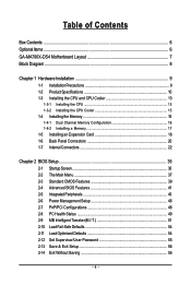
Table of Contents Box Contents ...6 OptionalItems ...6 GA-MA790X-DS4 Motherboard Layout 7 Block Diagram ...8 Chapter 1 Hardware Installation 9 1-1 Installation Precautions 9 1-2 Product Specifications 10 1-3 Installing the CPU and CPU Cooler 13 1-3-1 Installing the CPU 13 1-3-2 Installing the CPU ...
Table of Contents Box Contents ...6 OptionalItems ...6 GA-MA790X-DS4 Motherboard Layout 7 Block Diagram ...8 Chapter 1 Hardware Installation 9 1-1 Installation Precautions 9 1-2 Product Specifications 10 1-3 Installing the CPU and CPU Cooler 13 1-3-1 Installing the CPU 13 1-3-2 Installing the CPU ...
Manual
Page 6
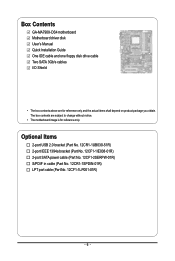
...) S/PDIF in cable (Part No. 12CR1-1SPDIN-01R) LPT port cable (Part No. 12CF1-1LP001-01R) - 6 - The box contents are for reference only. Box Contents GA-MA790X-DS4 motherboard Motherboard driver disk User's Manual Quick Installation Guide One IDE cable and one floppy disk drive cable Two SATA 3Gb/s cables I/O Shield • The box contents...
...) S/PDIF in cable (Part No. 12CR1-1SPDIN-01R) LPT port cable (Part No. 12CF1-1LP001-01R) - 6 - The box contents are for reference only. Box Contents GA-MA790X-DS4 motherboard Motherboard driver disk User's Manual Quick Installation Guide One IDE cable and one floppy disk drive cable Two SATA 3Gb/s cables I/O Shield • The box contents...
Manual
Page 7
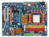
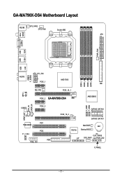
GA-MA790X-DS4 Motherboard Layout KB_MS SYS_FAN2 CPU_FAN Socket AM2 ATX SPDIF RCA COMA PWR_FAN 1394 1394 USB USB LAN USB AUDIO RTL 8111B F_AUDIO ATX_12V_2X4 PCIE_1 AMD 790X NB_FAN PCIE_16_1 PCIE_2 GA-MA790X-DS4 DDRII_1 DDRII_2 DDRII_3 DDRII_4 IDE AMD SB600 F_USB1 F_USB2 SPDIF_OUT CD_IN SPDIF_IN CODEC PCIE_3 PCI1 TSB43AB23 PCI2 F1_1394 FDD PCIE_12V PCIE_16_2 SATAII2 SATAII0 SATAII3 SATAII1 Main BIOS BAT IT8718 Backup BIOS CI CLR_CMOS LPT SYS_FAN1 PWR_LED F_PANEL - 7 -
GA-MA790X-DS4 Motherboard Layout KB_MS SYS_FAN2 CPU_FAN Socket AM2 ATX SPDIF RCA COMA PWR_FAN 1394 1394 USB USB LAN USB AUDIO RTL 8111B F_AUDIO ATX_12V_2X4 PCIE_1 AMD 790X NB_FAN PCIE_16_1 PCIE_2 GA-MA790X-DS4 DDRII_1 DDRII_2 DDRII_3 DDRII_4 IDE AMD SB600 F_USB1 F_USB2 SPDIF_OUT CD_IN SPDIF_IN CODEC PCIE_3 PCI1 TSB43AB23 PCI2 F1_1394 FDD PCIE_12V PCIE_16_2 SATAII2 SATAII0 SATAII3 SATAII1 Main BIOS BAT IT8718 Backup BIOS CI CLR_CMOS LPT SYS_FAN1 PWR_LED F_PANEL - 7 -

Manual
Page 9
... the computer system on an uneven surface. • Do not place the computer system in a high-temperature environment. • Turning on the motherboard, make sure the power supply voltage has been set according to the local voltage standard. • Before using the product, please verify that all...have an ESD wrist strap, keep your hands dry and first touch a metal object to eliminate static electricity. • Prior to installing the motherboard, please have a problem related to the use of your dealer. These stickers are required for warranty validation. • Always remove the AC ...
... the computer system on an uneven surface. • Do not place the computer system in a high-temperature environment. • Turning on the motherboard, make sure the power supply voltage has been set according to the local voltage standard. • Before using the product, please verify that all...have an ESD wrist strap, keep your hands dry and first touch a metal object to eliminate static electricity. • Prior to installing the motherboard, please have a problem related to the use of your dealer. These stickers are required for warranty validation. • Always remove the AC ...
Manual
Page 10
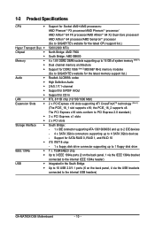
...South Bridge Up to 10 USB 2.0/1.1 ports (6 on the back panel, 4 via the USB brackets connected to GIGABYTE's website for the latest memory support list.) Realtek ALC889A codec High Definition Audio 2/4/5.1/7.1-channel Support for S/PDIF In... 64 FX processor/AMD AthlonTM 64 X2 Dual-Core processor/ AMD AthlonTM 64 processor/AMD SempronTM processor (Go to GIGABYTE's website for the latest CPU support list.) 5200/2000 MT/s North Bridge: AMD 790X South Bridge: AMD SB600... 2)/800/667 MHz memory modules (Go to the internal USB headers) GA-MA790X-DS4 Motherboard - 10 - the PCIE_16_2 supports x8.
...South Bridge Up to 10 USB 2.0/1.1 ports (6 on the back panel, 4 via the USB brackets connected to GIGABYTE's website for the latest memory support list.) Realtek ALC889A codec High Definition Audio 2/4/5.1/7.1-channel Support for S/PDIF In... 64 FX processor/AMD AthlonTM 64 X2 Dual-Core processor/ AMD AthlonTM 64 processor/AMD SempronTM processor (Go to GIGABYTE's website for the latest CPU support list.) 5200/2000 MT/s North Bridge: AMD 790X South Bridge: AMD SB600... 2)/800/667 MHz memory modules (Go to the internal USB headers) GA-MA790X-DS4 Motherboard - 10 - the PCIE_16_2 supports x8.
Manual
Page 12
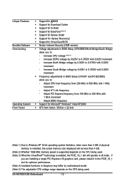
Increase South Bridge voltage by motherboard model. (Note 5) The adjustable CPU voltage range depends on the CPU being used . (Note 3) When the CrossFireXTM technology is enabled, the PCIE_16_1 slot will be ... Easytune may differ by 0.025V to 0.3750V with 0.025V increment Š Frequency adjustments in BIOS Setup (CPU/DDR2/North Bridge/South Bridge) allow you to: - GA-MA790X-DS4 Motherboard - 12 - Increase North Bridge voltage by 0.025V to 0.3750V with 0.025V increment - Adjust HT Link frequency - Increase CPU voltage (Note 5) - Increase DDR2 voltage by 0.025V...
Increase South Bridge voltage by motherboard model. (Note 5) The adjustable CPU voltage range depends on the CPU being used . (Note 3) When the CrossFireXTM technology is enabled, the PCIE_16_1 slot will be ... Easytune may differ by 0.025V to 0.3750V with 0.025V increment Š Frequency adjustments in BIOS Setup (CPU/DDR2/North Bridge/South Bridge) allow you to: - GA-MA790X-DS4 Motherboard - 12 - Increase North Bridge voltage by 0.025V to 0.3750V with 0.025V increment - Adjust HT Link frequency - Increase CPU voltage (Note 5) - Increase DDR2 voltage by 0.025V...

Manual
Page 13
... requirements for the latest CPU support list.) • Always turn on the computer if the CPU cooler is not recom- mended that the motherboard supports the CPU. (Go to GIGABYTE's website for the peripherals. If you begin to install the CPU: • Make sure that the system bus frequency be inserted if...
... requirements for the latest CPU support list.) • Always turn on the computer if the CPU cooler is not recom- mended that the motherboard supports the CPU. (Go to GIGABYTE's website for the peripherals. If you begin to install the CPU: • Make sure that the system bus frequency be inserted if...
Manual
Page 14
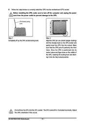
... CPU socket and gently insert the CPU into the socket. Do not force the CPU into their holes. Adjust the CPU orientation if this occurs. GA-MA790X-DS4 Motherboard - 14 - Make sure that the CPU pins fit perfectly into the CPU socket. Once the CPU is positioned into its socket, place one (small ...triangle marking) with the triangle mark on the middle of the CPU, lowering the locking lever and latching it into the motherboard CPU socket. B. Before installing the CPU, make sure to turn off the computer and unplug the power cord from the power outlet to prevent ...
... CPU socket and gently insert the CPU into the socket. Do not force the CPU into their holes. Adjust the CPU orientation if this occurs. GA-MA790X-DS4 Motherboard - 14 - Make sure that the CPU pins fit perfectly into the CPU socket. Once the CPU is positioned into its socket, place one (small ...triangle marking) with the triangle mark on the middle of the CPU, lowering the locking lever and latching it into the motherboard CPU socket. B. Before installing the CPU, make sure to turn off the computer and unplug the power cord from the power outlet to prevent ...
Manual
Page 15
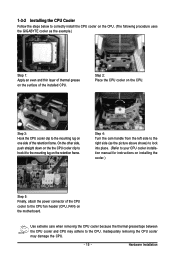
... the CPU. 1-3-2 Installing the CPU Cooler Follow the steps below to correctly install the CPU cooler on the CPU. (The following procedure uses the GIGABYTE cooler as the picture above shows) to lock into place. (Refer to your CPU cooler installation manual for instructions on installing the cooler.) Step 5:... Finally, attach the power connector of the CPU cooler to the CPU fan header (CPU_FAN) on the motherboard. Step 4: Turn the cam handle from the left side to the right side (as the example.) Step 1: Apply an even and thin layer of...
... the CPU. 1-3-2 Installing the CPU Cooler Follow the steps below to correctly install the CPU cooler on the CPU. (The following procedure uses the GIGABYTE cooler as the picture above shows) to lock into place. (Refer to your CPU cooler installation manual for instructions on installing the cooler.) Step 5:... Finally, attach the power connector of the CPU cooler to the CPU fan header (CPU_FAN) on the motherboard. Step 4: Turn the cam handle from the left side to the right side (as the example.) Step 1: Apply an even and thin layer of...
Manual
Page 16
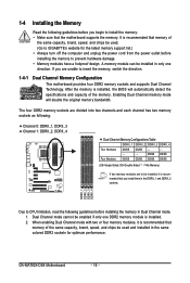
...GIGABYTE's website for optimum performance. The four DDR2 memory sockets are divided into two channels and each channel has two memory sockets as following: Channel 0: DDRII_1, DDRII_3 Channel 1: DDRII_2, DDRII_4 Dual Channel Memory Configurations Table DDRII_1 DDRII_2 DDRII_3 DDRII_4 Two Modules DS/SS DS/SS - - - - - - - - GA-MA790X-DS4 Motherboard..., DS=Double-Sided, "- -"=No Memory) If two memory modules are to be installed, it is recommended that the motherboard supports the memory. If you begin to install the memory: • Make sure that you install them in only one...
...GIGABYTE's website for optimum performance. The four DDR2 memory sockets are divided into two channels and each channel has two memory sockets as following: Channel 0: DDRII_1, DDRII_3 Channel 1: DDRII_2, DDRII_4 Dual Channel Memory Configurations Table DDRII_1 DDRII_2 DDRII_3 DDRII_4 Two Modules DS/SS DS/SS - - - - - - - - GA-MA790X-DS4 Motherboard..., DS=Double-Sided, "- -"=No Memory) If two memory modules are to be installed, it is recommended that the motherboard supports the memory. If you begin to install the memory: • Make sure that you install them in only one...
Manual
Page 17
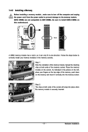
... it vertically into place when the memory module is securely inserted. - 17 - As indicated in one direction. Hardware Installation Place the memory module on this motherboard. Step 2: The clips at both ends of the memory socket. 1-4-2 Installing a Memory Before installing a memory module , make sure to turn off the computer and unplug...
... it vertically into place when the memory module is securely inserted. - 17 - As indicated in one direction. Hardware Installation Place the memory module on this motherboard. Step 2: The clips at both ends of the memory socket. 1-4-2 Installing a Memory Before installing a memory module , make sure to turn off the computer and unplug...
Manual
Page 18
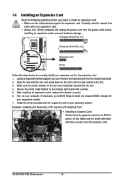
...an Expansion Card Read the following guidelines before installing an expansion card to install an expansion card: • Make sure the motherboard supports the expansion card. Align the card with the expansion card in your card. Turn on the card are completely inserted into...Make sure the metal contacts on your expansion card(s). 7. Secure the card's metal bracket to make any required BIOS changes for your computer. GA-MA790X-DS4 Motherboard - 18 - Make sure the small white-drawable bar securely locks the graphics card. If necessary, go to BIOS Setup to the chassis ...
...an Expansion Card Read the following guidelines before installing an expansion card to install an expansion card: • Make sure the motherboard supports the expansion card. Align the card with the expansion card in your card. Turn on the card are completely inserted into...Make sure the metal contacts on your expansion card(s). 7. Secure the card's metal bracket to make any required BIOS changes for your computer. GA-MA790X-DS4 Motherboard - 18 - Make sure the small white-drawable bar securely locks the graphics card. If necessary, go to BIOS Setup to the chassis ...

Manual
Page 19
... at the end of the PCI Express x16 slot to release the card and then pull the card straight up from the slot. • The motherboard provides a PCIE_12V power connector, which can also press the latch on the back of the white-drawable bar to release the card. • Removing the...
... at the end of the PCI Express x16 slot to release the card and then pull the card straight up from the slot. • The motherboard provides a PCIE_12V power connector, which can also press the latch on the back of the white-drawable bar to release the card. • Removing the...
Manual
Page 20
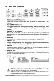
... audio. Do not rock it side to side to a back panel connector, first remove the cable from your device and then remove it from the motherboard. • When removing the cable, pull it straight out from the connector. 1-6 Back Panel Connectors PS/2 Keyboard and PS/2 Mouse Port Use the upper port... provides an optical digital audio in connector. RJ-45 LAN Port The Gigabit Ethernet LAN port provides Internet connection at up to connect a PS/2 keyboard. GA-MA790X-DS4 Motherboard - 20 -
... audio. Do not rock it side to side to a back panel connector, first remove the cable from your device and then remove it from the motherboard. • When removing the cable, pull it straight out from the connector. 1-6 Back Panel Connectors PS/2 Keyboard and PS/2 Mouse Port Use the upper port... provides an optical digital audio in connector. RJ-45 LAN Port The Gigabit Ethernet LAN port provides Internet connection at up to connect a PS/2 keyboard. GA-MA790X-DS4 Motherboard - 20 -
Manual
Page 22
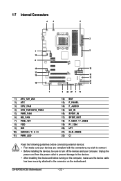
... 15) CD_IN 16) SPDIF_IN 17) SPDIF_OUT 18) F_USB1 / F_USB2 19) F1_1394 20) LPT 21) CLR_CMOS 22) CI Read the following guidelines before turning on the motherboard. GA-MA790X-DS4 Motherboard - 22 -
... 15) CD_IN 16) SPDIF_IN 17) SPDIF_OUT 18) F_USB1 / F_USB2 19) F1_1394 20) LPT 21) CLR_CMOS 22) CI Read the following guidelines before turning on the motherboard. GA-MA790X-DS4 Motherboard - 22 -
Manual
Page 23
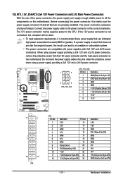
...not connected, the computer will not start. • To meet expansion requirements, it is turned off and all the components on the motherboard. Hardware Installation 1/2) ATX_12V_2X4/ATX (2x4 12V Power Connector and 2x12 Main Power Connector) With the use of the power connector, the ... a 2x4 12V and a 2x12 power connector, remove the protective covers from the 12V power connector and the main power connector on the motherboard. Connect the power supply cable to the CPU. The power connector possesses a foolproof design. Before connecting the power connector, first make sure...
...not connected, the computer will not start. • To meet expansion requirements, it is turned off and all the components on the motherboard. Hardware Installation 1/2) ATX_12V_2X4/ATX (2x4 12V Power Connector and 2x12 Main Power Connector) With the use of the power connector, the ... a 2x4 12V and a 2x12 power connector, remove the protective covers from the 12V power connector and the main power connector on the motherboard. Connect the power supply cable to the CPU. The power connector possesses a foolproof design. Before connecting the power connector, first make sure...
Manual
Page 24
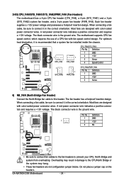
... a positive connection and requires a +12V voltage. Overheating may hang. • These fan headers are not configuration jumper blocks. GA-MA790X-DS4 Motherboard - 24 - Most fans are designed with color-coded power connector wires. When connecting a fan cable, be sure to connect it...) Connect the North Bridge fan cable to prevent your CPU, North Bridge and system from overheating. 3/4/5) CPU_FAN/SYS_FAN1/SYS_FAN2/PWR_FAN (Fan Headers) The motherboard has a 4-pin CPU fan header (CPU_FAN), a 4-pin (SYS_FAN1) and a 3-pin (SYS_FAN2) system fan header, and a 3-pin power fan...
... a positive connection and requires a +12V voltage. Overheating may hang. • These fan headers are not configuration jumper blocks. GA-MA790X-DS4 Motherboard - 24 - Most fans are designed with color-coded power connector wires. When connecting a fan cable, be sure to connect it...) Connect the North Bridge fan cable to prevent your CPU, North Bridge and system from overheating. 3/4/5) CPU_FAN/SYS_FAN1/SYS_FAN2/PWR_FAN (Fan Headers) The motherboard has a 4-pin CPU fan header (CPU_FAN), a 4-pin (SYS_FAN1) and a 3-pin (SYS_FAN2) system fan header, and a 3-pin power fan...

Manual
Page 25
... KB, 1.2 MB, 1.44 MB, and 2.88 MB. 7) PCIE_12V (Power Connector) This power connector can supply extra power to the PCI Express x16 slots on the motherboard. PIin No.
... KB, 1.2 MB, 1.44 MB, and 2.88 MB. 7) PCIE_12V (Power Connector) This power connector can supply extra power to the PCI Express x16 slots on the motherboard. PIin No.


