
Manual
Page 4
Table of Contents Box Contents...6 Optional Items...6 GA-MA78LM-S2H/GA-MA78LM-S2 Motherboard Layout 7 Block Diagram...8 Chapter 1 Hardware Installation 9 1-1 Installation Precautions 9 1-2 Product Specifications 10 1-3 Installing the CPU and CPU Cooler 13 1-3-1 Installing the CPU 13 1-3-2 Installing the CPU Cooler 15 1-4 Installing the Memory 16 1-4-1 Dual Channel Memory Configuration 16 1-4-2 Installing a Memory 17 1-5 Installing an Expansion Card 18 1-6 Back...
Table of Contents Box Contents...6 Optional Items...6 GA-MA78LM-S2H/GA-MA78LM-S2 Motherboard Layout 7 Block Diagram...8 Chapter 1 Hardware Installation 9 1-1 Installation Precautions 9 1-2 Product Specifications 10 1-3 Installing the CPU and CPU Cooler 13 1-3-1 Installing the CPU 13 1-3-2 Installing the CPU Cooler 15 1-4 Installing the Memory 16 1-4-1 Dual Channel Memory Configuration 16 1-4-2 Installing a Memory 17 1-5 Installing an Expansion Card 18 1-6 Back...
Manual
Page 8
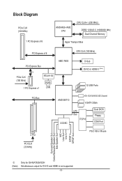
Block Diagram PCIe CLK (100 MHz) 1 PCI Express x16 AM3/AM2+/AM2 CPU CPU CLK+/- (200 MHz) DDR2 1200(O.C.)1066/800 MHz Dual Channel Memory Hyper Transport Bus PCI Express x16 GFX CLK (100 MHz) PCI Express Bus x1 PCIe CLK (100 MHz) 1 PCI Express x1 RTL8111D RJ45 LAN AMD ... CLK (33 MHz) Surround Speaker Out Center/Subwoofer Speaker Out Side Speaker Out MIC Line Out Line In S/PDIF In S/PDIF Out j (Note) Only for GA-MA78LM-S2H Simultaneous output for DVI-D and HDMI is not supported. - 8 -
Block Diagram PCIe CLK (100 MHz) 1 PCI Express x16 AM3/AM2+/AM2 CPU CPU CLK+/- (200 MHz) DDR2 1200(O.C.)1066/800 MHz Dual Channel Memory Hyper Transport Bus PCI Express x16 GFX CLK (100 MHz) PCI Express Bus x1 PCIe CLK (100 MHz) 1 PCI Express x1 RTL8111D RJ45 LAN AMD ... CLK (33 MHz) Surround Speaker Out Center/Subwoofer Speaker Out Side Speaker Out MIC Line Out Line In S/PDIF In S/PDIF Out j (Note) Only for GA-MA78LM-S2H Simultaneous output for DVI-D and HDMI is not supported. - 8 -

Manual
Page 9
... components. • When connecting hardware components to the internal connectors on the computer power during the installation process can become damaged as a motherboard, CPU or memory.
... components. • When connecting hardware components to the internal connectors on the computer power during the installation process can become damaged as a motherboard, CPU or memory.
Manual
Page 10
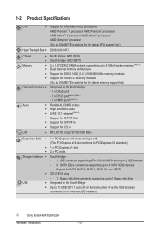
... Bridge: AMD SB710 2 x 1.8V DDR2 DIMM sockets supporting up to 8 GB of system memory (Note 1) Dual channel memory architecture Support for DDR2 1200 (O.C.)/1066/800 MHz memory modules Support for non-ECC memory modules (Go to GIGABYTE's website for the latest memory support list.) Integrated in the South Bridge Up to 12 USB 2.0/1.1 ports (8 on the... - 1 x DVI-D port (Note 2) (Note 3) - 1 x HDMI port j(Note 3) Realtek ALC888B codec High Definition Audio 2/4/5.1/7.1-channel (Note 4) Support for S/PDIF Out Support for S/PDIF In Support for GA-MA78LM-S2H Hardware Installation - 10 -
... Bridge: AMD SB710 2 x 1.8V DDR2 DIMM sockets supporting up to 8 GB of system memory (Note 1) Dual channel memory architecture Support for DDR2 1200 (O.C.)/1066/800 MHz memory modules Support for non-ECC memory modules (Go to GIGABYTE's website for the latest memory support list.) Integrated in the South Bridge Up to 12 USB 2.0/1.1 ports (8 on the... - 1 x DVI-D port (Note 2) (Note 3) - 1 x HDMI port j(Note 3) Realtek ALC888B codec High Definition Audio 2/4/5.1/7.1-channel (Note 4) Support for S/PDIF Out Support for S/PDIF In Support for GA-MA78LM-S2H Hardware Installation - 10 -
Manual
Page 12
... Form Factor; 24.3cm x 22.0cm (Note 1) Due to Windows Vista/XP 32-bit operating system limitation, when more than 4 GB of physical memory is installed, the actual memory size displayed will be less than 4 GB. (Note 2) The DVI-D port does not support D-Sub connection by adapter. (Note 3) Simultaneous output for DVI...
... Form Factor; 24.3cm x 22.0cm (Note 1) Due to Windows Vista/XP 32-bit operating system limitation, when more than 4 GB of physical memory is installed, the actual memory size displayed will be less than 4 GB. (Note 2) The DVI-D port does not support D-Sub connection by adapter. (Note 3) Simultaneous output for DVI...

Manual
Page 13
... the CPU. If you wish to set beyond the standard specifications, please do so according to your hardware specifications including the CPU, graphics card, memory, hard drive, etc. 1-3-1 Installing the CPU A. A Small Triangle Mark Denotes Pin One of the CPU. It is not installed, otherwise overheating... CPU. • Do not turn on the computer if the CPU cooler is not recommended that the motherboard supports the CPU. (Go to GIGABYTE's website for the peripherals. 1-3 Installing the CPU and CPU Cooler Read the following guidelines before you begin to install the CPU: • ...
... the CPU. If you wish to set beyond the standard specifications, please do so according to your hardware specifications including the CPU, graphics card, memory, hard drive, etc. 1-3-1 Installing the CPU A. A Small Triangle Mark Denotes Pin One of the CPU. It is not installed, otherwise overheating... CPU. • Do not turn on the computer if the CPU cooler is not recommended that the motherboard supports the CPU. (Go to GIGABYTE's website for the peripherals. 1-3 Installing the CPU and CPU Cooler Read the following guidelines before you begin to install the CPU: • ...

Manual
Page 16
... install the memory: • Make sure that memory of the memory. After the memory is installed. 2. A memory module can be used . (Go to insert the memory, switch the direction. 1-4-1 Dual Channel Memory Configuration This motherboard provides two DDR2 memory sockets and supports Dual Channel Technology. The two DDR2 memory sockets are unable to GIGABYTE's website for the latest memory support list...
... install the memory: • Make sure that memory of the memory. After the memory is installed. 2. A memory module can be used . (Go to insert the memory, switch the direction. 1-4-1 Dual Channel Memory Configuration This motherboard provides two DDR2 memory sockets and supports Dual Channel Technology. The two DDR2 memory sockets are unable to GIGABYTE's website for the latest memory support list...

Manual
Page 17
...Step 1: Note the orientation of the memory socket. Place the memory module on the memory and insert it can only fit in the memory sockets. As indicated in the picture on the left, place your memory modules in one direction. 1-4-2 Installing a Memory Before installing a memory module , make sure to turn ... of the socket will snap into the memory socket. Step 2: The clips at both ends of the memory, push down on the socket. Hardware Installation Notch DDR2 DIMM A DDR2 memory module has a notch, so it vertically into place when the memory module is securely inserted. - 17 -...
...Step 1: Note the orientation of the memory socket. Place the memory module on the memory and insert it can only fit in the memory sockets. As indicated in the picture on the left, place your memory modules in one direction. 1-4-2 Installing a Memory Before installing a memory module , make sure to turn ... of the socket will snap into the memory socket. Step 2: The clips at both ends of the memory, push down on the socket. Hardware Installation Notch DDR2 DIMM A DDR2 memory module has a notch, so it vertically into place when the memory module is securely inserted. - 17 -...

Manual
Page 20
... B. Do not rock it straight out from the connector. The table below . • CPU: AMD Phenom™ X3 processor or above • Memory: Two 1 GB DDR2 800 MHz memory modules with dual channel mode enabled • BIOS Setup: At least 256 MB of the LAN port LEDs. Connection/ Speed LED Activity LED...
... B. Do not rock it straight out from the connector. The table below . • CPU: AMD Phenom™ X3 processor or above • Memory: Two 1 GB DDR2 800 MHz memory modules with dual channel mode enabled • BIOS Setup: At least 256 MB of the LAN port LEDs. Connection/ Speed LED Activity LED...

Manual
Page 34
..., you wish to load, then press to complete. MB Intelligent Tweaker(M.I.T.) Use this menu to configure the clock, frequency and voltages of your CPU, memory, etc. Standard CMOS Features Use this menu to configure the system time and date, hard drive types, floppy disk drive types, and the type...
..., you wish to load, then press to complete. MB Intelligent Tweaker(M.I.T.) Use this menu to configure the clock, frequency and voltages of your CPU, memory, etc. Standard CMOS Features Use this menu to configure the system time and date, hard drive types, floppy disk drive types, and the type...

Manual
Page 35
... settings. (Note) This item appears only if you set the System Voltage Control item to Auto to CPU, chipset, or memory and reduce the useful life of these components. This page is for advanced users only and we recommend you made is recommended... Control x CPU Frequency(MHz) PCIE Clock(MHz) HT Link Width HT Link Frequency VGA Core Clock control x VGA Core Clock(MHz) Set Memory Clock x Memory Clock System Voltage Optimized ******** System Voltage Control x DDR2 Voltage Control x NorthBridge Volt Control x SouthBridge Volt Control x CPU NB VID Control x...
... settings. (Note) This item appears only if you set the System Voltage Control item to Auto to CPU, chipset, or memory and reduce the useful life of these components. This page is for advanced users only and we recommend you made is recommended... Control x CPU Frequency(MHz) PCIE Clock(MHz) HT Link Width HT Link Frequency VGA Core Clock control x VGA Core Clock(MHz) Set Memory Clock x Memory Clock System Voltage Optimized ******** System Voltage Control x DDR2 Voltage Control x NorthBridge Volt Control x SouthBridge Volt Control x CPU NB VID Control x...

Manual
Page 37
...Auto BIOS will automatically adjust the HT Link Frequency. (Default) 200 MHz~2.6 GHz Sets HT Link Frequency to X4.00. Set Memory Clock Determines whether to manually set the memory clock. Auto sets the PCIe clock frequency to standard 100 MHz. (Default: Auto) HT Link Width Allows you to manually set ...the width for the HT Link between the CPU and chipset. Manual allows the memory clock control item below to X5.33. (Note) This item appears only if you install a CPU that the CPU frequency be configurable. (Default: Auto...
...Auto BIOS will automatically adjust the HT Link Frequency. (Default) 200 MHz~2.6 GHz Sets HT Link Frequency to X4.00. Set Memory Clock Determines whether to manually set the memory clock. Auto sets the PCIe clock frequency to standard 100 MHz. (Default: Auto) HT Link Width Allows you to manually set ...the width for the HT Link between the CPU and chipset. Manual allows the memory clock control item below to X5.33. (Note) This item appears only if you install a CPU that the CPU frequency be configurable. (Default: Auto...

Manual
Page 38
... Control Allows you to 0.300V at 0.1V increment. Normal Supplies the South Bridge voltage as required. (Default) +0.100V ~ +0.300V Increases memory voltage by 0.100V to set memory voltage. CPU Voltage Control Allows you to 0.3V at 0.1V increment. Auto sets the CPU voltage as required. BIOS Setup - 38 -... When you use an AM2 CPU: DDR 400 Sets Memory Clock to DDR 533. DDR 533 Sets Memory Clock to DDR 400. Note: Increasing memory voltage may result in damage to manually set the CPU Northbridge VID voltage. Auto lets the BIOS ...
... Control Allows you to 0.300V at 0.1V increment. Normal Supplies the South Bridge voltage as required. (Default) +0.100V ~ +0.300V Increases memory voltage by 0.100V to set memory voltage. CPU Voltage Control Allows you to 0.3V at 0.1V increment. Auto sets the CPU voltage as required. BIOS Setup - 38 -... When you use an AM2 CPU: DDR 400 Sets Memory Clock to DDR 533. DDR 533 Sets Memory Clock to DDR 400. Note: Increasing memory voltage may result in damage to manually set the CPU Northbridge VID voltage. Auto lets the BIOS ...

Manual
Page 39
... 3 Master } IDE Channel 3 Slave [None] [None] [None] [None] [None] [None] [None] [None] Drive A Floppy 3 Mode Support [1.44M, 3.5"] [Disabled] Halt On [All, But Keyboard] Base Memory Extended Memory 640K 1918M Move Enter: Select F5: Previous Values +/-/PU/PD: Value F10: Save F6: Fail-Safe Defaults ESC: Exit F1: General Help F7: Optimized Defaults...
... 3 Master } IDE Channel 3 Slave [None] [None] [None] [None] [None] [None] [None] [None] Drive A Floppy 3 Mode Support [1.44M, 3.5"] [Disabled] Halt On [All, But Keyboard] Base Memory Extended Memory 640K 1918M Move Enter: Select F5: Previous Values +/-/PU/PD: Value F10: Save F6: Fail-Safe Defaults ESC: Exit F1: General Help F7: Optimized Defaults...

Manual
Page 40
...other errors. Typically, 640 KB will stop for an error during the POST. Extended Memory The amount of the currently installed hard drive. Capacity Approximate capacity of extended memory. All, But Keyboard The system boot will not stop for a keyboard error but...Options are : Disabled (default), Drive A. Cylinder Number of sectors. Sector Number of cylinders. Base Memory Also called conventional memory. The following fields display your system. Memory These fields are read-only and are determined by the BIOS POST. Head Number of floppy disk ...
...other errors. Typically, 640 KB will stop for an error during the POST. Extended Memory The amount of the currently installed hard drive. Capacity Approximate capacity of extended memory. All, But Keyboard The system boot will not stop for a keyboard error but...Options are : Disabled (default), Drive A. Cylinder Number of sectors. Sector Number of cylinders. Base Memory Also called conventional memory. The following fields display your system. Memory These fields are read-only and are determined by the BIOS POST. Head Number of floppy disk ...

Manual
Page 41
... F10: Save F6: Fail-Safe Defaults ESC: Exit F1: General Help F7: Optimized Defaults Internal Graphics Mode Allows you install a CPU that supports this memory for GA-MA78LM-S2H (Note) This item appears only if you to determine whether to PEG and an ATI graphics card is installed. (Default: Disabled) Onboard VGA output connect...
... F10: Save F6: Fail-Safe Defaults ESC: Exit F1: General Help F7: Optimized Defaults Internal Graphics Mode Allows you install a CPU that supports this memory for GA-MA78LM-S2H (Note) This item appears only if you to determine whether to PEG and an ATI graphics card is installed. (Default: Disabled) Onboard VGA output connect...

Manual
Page 47
...) for the password, press again without entering the password to its last known awake state upon the return of power from an AC power loss. Memory The system returns to clear the password settings. BIOS Setup PME Event Wake Up Allows the system to be awakened from an ACPI sleep state...
...) for the password, press again without entering the password to its last known awake state upon the return of power from an AC power loss. Memory The system returns to clear the password settings. BIOS Setup PME Event Wake Up Allows the system to be awakened from an ACPI sleep state...
Manual
Page 59
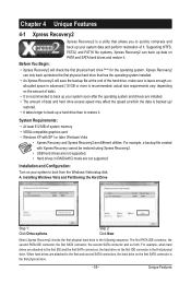
... and back up your system data and perform restoration of data and hard drive access speed may affect the speed at the end of system memory • VESA compatible graphics card • Windows XP with Xpress Recovery cannot be restored using Xpress Recovery2. • USB hard drives are not supported. •...
... and back up your system data and perform restoration of data and hard drive access speed may affect the speed at the end of system memory • VESA compatible graphics card • Windows XP with Xpress Recovery cannot be restored using Xpress Recovery2. • USB hard drives are not supported. •...

Manual
Page 66
... (.wav file). (Note) Before enabling Easy Boost, right-click the EasyTune 6 icon in Easy mode/Advanced mode, be changed linearly based on the installed memory module(s). 4-3 EasyTune 6 GIGABYTE's EasyTune 6 is a simple and easy-to-use auto-overclocking function . (Note) When activated, the system automatically experiments all sorts of overclocking configurations till it...
... (.wav file). (Note) Before enabling Easy Boost, right-click the EasyTune 6 icon in Easy mode/Advanced mode, be changed linearly based on the installed memory module(s). 4-3 EasyTune 6 GIGABYTE's EasyTune 6 is a simple and easy-to-use auto-overclocking function . (Note) When activated, the system automatically experiments all sorts of overclocking configurations till it...

Manual
Page 71
... assigned to arrays, press to enter FastBuild (tm) Utility" (Figure 2). RAID Option ROM Version 3.0.1540.47 (c) 2008 Advanced Micro Devices, Inc. Step 1: After the POST memory test begins and before the operating system boot begins, look for a non-RAID configuration. No Array is the first option screen when you enter the...
... assigned to arrays, press to enter FastBuild (tm) Utility" (Figure 2). RAID Option ROM Version 3.0.1540.47 (c) 2008 Advanced Micro Devices, Inc. Step 1: After the POST memory test begins and before the operating system boot begins, look for a non-RAID configuration. No Array is the first option screen when you enter the...


