Manual
Page 1
GA-MA785GPMT-UD2H/ GA-MA785GMT-UD2H/ GA-MA785GMT-US2H AM3 socket motherboard for AMD Phenom™ II processor/ AMD Athlon™ II processor User's Manual Rev. 1101 12ME-MA785T2-1101R
GA-MA785GPMT-UD2H/ GA-MA785GMT-UD2H/ GA-MA785GMT-US2H AM3 socket motherboard for AMD Phenom™ II processor/ AMD Athlon™ II processor User's Manual Rev. 1101 12ME-MA785T2-1101R
Manual
Page 2
Motherboard GA-MA785GPMT-UD2H/GA-MA785GMT-UD2H/GA-MA785GMT-US2H July 16, 2009 Motherboard GA-MA785GPMT-UD2H/ GA-MA785GMT-UD2H/ GA-MA785GMT-US2H July 16, 2009
Motherboard GA-MA785GPMT-UD2H/GA-MA785GMT-UD2H/GA-MA785GMT-US2H July 16, 2009 Motherboard GA-MA785GPMT-UD2H/ GA-MA785GMT-UD2H/ GA-MA785GMT-US2H July 16, 2009
Manual
Page 3
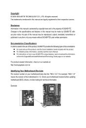
...For product-related information, check on our website at: http://www.gigabyte.com.tw Identifying Your Motherboard Revision The revision number on our website. The trademarks mentioned in the use GIGABYTE's unique features, read the User's Manual. Disclaimer Information in any ...form or by copyright laws and is the property of the motherboard is 1.0. Check your motherboard looks like this manual are legally registered to ...
...For product-related information, check on our website at: http://www.gigabyte.com.tw Identifying Your Motherboard Revision The revision number on our website. The trademarks mentioned in the use GIGABYTE's unique features, read the User's Manual. Disclaimer Information in any ...form or by copyright laws and is the property of the motherboard is 1.0. Check your motherboard looks like this manual are legally registered to ...
Manual
Page 4
Table of Contents Box Contents...6 Optional Items...6 GA-MA785GPMT-UD2H/GA-MA785GMT-UD2H(US2H 7 Motherboard Layout...7 Block Diagram...8 Chapter 1 Hardware Installation 9 1-1 Installation Precautions 9 1-2 Product Specifications 10 1-3 Installing the CPU and CPU Cooler 13 1-3-1 Installing the CPU 13 1-3-2 Installing the CPU ...
Table of Contents Box Contents...6 Optional Items...6 GA-MA785GPMT-UD2H/GA-MA785GMT-UD2H(US2H 7 Motherboard Layout...7 Block Diagram...8 Chapter 1 Hardware Installation 9 1-1 Installation Precautions 9 1-2 Product Specifications 10 1-3 Installing the CPU and CPU Cooler 13 1-3-1 Installing the CPU 13 1-3-2 Installing the CPU ...
Manual
Page 6
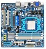
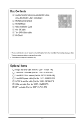
Box Contents GA-MA785GPMT-UD2H, GA-MA785GMT-UD2H, or GA-MA785GMT-US2H motherboard Motherboard driver disk User's Manual Quick Installation Guide One IDE cable Two SATA 3Gb/s cables I/O Shield • The box contents above are subject to change without notice. • The motherboard image is for reference only and the actual items shall depend on the product package you obtain...
Box Contents GA-MA785GPMT-UD2H, GA-MA785GMT-UD2H, or GA-MA785GMT-US2H motherboard Motherboard driver disk User's Manual Quick Installation Guide One IDE cable Two SATA 3Gb/s cables I/O Shield • The box contents above are subject to change without notice. • The motherboard image is for reference only and the actual items shall depend on the product package you obtain...
Manual
Page 7
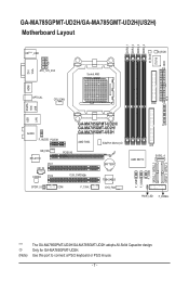
... a PS/2 keyboard or PS/2 mouse. - 7 - DDR3_1 DDR3_2 DDR3_3 DDR3_4 M_BIOS IT8718 ATX GA-MA785GPMT-UD2H/GA-MA785GMT-UD2H(US2H) Motherboard Layout DVI VGA KB(Note)_USB ATX_12V_2X4 Socket AM3 B_BIOS CI HDMI USB ESATA 1394 OPTICAL CPU_FAN FDD USB LAN AUDIO F_AUDIO PCIEX1 GA-MA785GPMT-UD2H/ GA-MA785GMT-UD2H/ GA-MA785GMT-US2H AMD 785G SidePort Memoryj NB_FAN RTL8111C PCI1 CD_IN CODEC PCI2...
... a PS/2 keyboard or PS/2 mouse. - 7 - DDR3_1 DDR3_2 DDR3_3 DDR3_4 M_BIOS IT8718 ATX GA-MA785GPMT-UD2H/GA-MA785GMT-UD2H(US2H) Motherboard Layout DVI VGA KB(Note)_USB ATX_12V_2X4 Socket AM3 B_BIOS CI HDMI USB ESATA 1394 OPTICAL CPU_FAN FDD USB LAN AUDIO F_AUDIO PCIEX1 GA-MA785GPMT-UD2H/ GA-MA785GMT-UD2H/ GA-MA785GMT-US2H AMD 785G SidePort Memoryj NB_FAN RTL8111C PCI1 CD_IN CODEC PCI2...

Manual
Page 9
...stickers are required for warranty validation. • Always remove the AC power by your hardware components are connected. • To prevent damage to the motherboard, do not have an ESD wrist strap, keep your hands dry and first touch a metal object to eliminate static electricity. • Prior to ...installing the motherboard, please have it on top of an antistatic pad or within the computer casing. • Do not place the computer system on an uneven ...
...stickers are required for warranty validation. • Always remove the AC power by your hardware components are connected. • To prevent damage to the motherboard, do not have an ESD wrist strap, keep your hands dry and first touch a metal object to eliminate static electricity. • Prior to ...installing the motherboard, please have it on top of an antistatic pad or within the computer casing. • Do not place the computer system on an uneven ...
Manual
Page 12
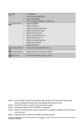
... CPU/system fan speed control function is supported will depend on the CPU/system cooler you install. (Note 5) Available functions in EasyTune may differ by motherboard model.
... CPU/system fan speed control function is supported will depend on the CPU/system cooler you install. (Note 5) Available functions in EasyTune may differ by motherboard model.

Manual
Page 13
... socket.) • Apply an even and thin layer of thermal grease on the computer if the CPU cooler is not recommended that the motherboard supports the CPU. (Go to GIGABYTE's website for the peripherals. A Small Triangle Mark Denotes Pin One of the CPU. Locate the pin one of the Socket AM3 Socket...
... socket.) • Apply an even and thin layer of thermal grease on the computer if the CPU cooler is not recommended that the motherboard supports the CPU. (Go to GIGABYTE's website for the peripherals. A Small Triangle Mark Denotes Pin One of the CPU. Locate the pin one of the Socket AM3 Socket...

Manual
Page 14
... fully locked position. B. The CPU cannot fit in if oriented incorrectly. Hardware Installation - 14 - Follow the steps below to correctly install the CPU into the motherboard CPU socket. • Before installing the CPU, make sure to turn off the computer and unplug the power cord from the power outlet to prevent...
... fully locked position. B. The CPU cannot fit in if oriented incorrectly. Hardware Installation - 14 - Follow the steps below to correctly install the CPU into the motherboard CPU socket. • Before installing the CPU, make sure to turn off the computer and unplug the power cord from the power outlet to prevent...

Manual
Page 15
...cooler may adhere to the mounting lug on the retention frame. Step 3: Hook the CPU cooler clip to the CPU fan header (CPU_FAN) on the motherboard. Use extreme care when removing the CPU cooler because the thermal grease/tape between the CPU cooler and CPU may damage the CPU. - 15 -...to the CPU. 1-3-2 Installing the CPU Cooler Follow the steps below to correctly install the CPU cooler on the CPU. (The following procedure uses the GIGABYTE cooler as the picture above shows) to lock into place. (Refer to your CPU cooler installation manual for instructions on installing the cooler.) Step 5:...
...cooler may adhere to the mounting lug on the retention frame. Step 3: Hook the CPU cooler clip to the CPU fan header (CPU_FAN) on the motherboard. Use extreme care when removing the CPU cooler because the thermal grease/tape between the CPU cooler and CPU may damage the CPU. - 15 -...to the CPU. 1-3-2 Installing the CPU Cooler Follow the steps below to correctly install the CPU cooler on the CPU. (The following procedure uses the GIGABYTE cooler as the picture above shows) to lock into place. (Refer to your CPU cooler installation manual for instructions on installing the cooler.) Step 5:...
Manual
Page 16
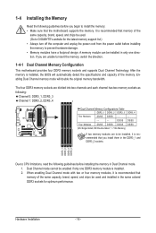
...memory: • Make sure that you are unable to insert the memory, switch the direction. 1-4-1 Dual Channel Memory Configuration This motherboard provides four DDR3 memory sockets and supports Dual Channel Technology. A memory module can be enabled if only one direction. If you ...Channel Memory Configurations Table DDR3_1 DDR3_2 DDR3_3 DDR3_4 Two Modules DS/SS DS/SS - - - - - - - - DDR3_1 DDR3_2 DDR3_3 DDR3_4 Due to GIGABYTE's website for optimum performance. The four DDR3 memory sockets are to prevent hardware damage. • Memory modules have a foolproof design. DS/SS DS/...
...memory: • Make sure that you are unable to insert the memory, switch the direction. 1-4-1 Dual Channel Memory Configuration This motherboard provides four DDR3 memory sockets and supports Dual Channel Technology. A memory module can be enabled if only one direction. If you ...Channel Memory Configurations Table DDR3_1 DDR3_2 DDR3_3 DDR3_4 Two Modules DS/SS DS/SS - - - - - - - - DDR3_1 DDR3_2 DDR3_3 DDR3_4 Due to GIGABYTE's website for optimum performance. The four DDR3 memory sockets are to prevent hardware damage. • Memory modules have a foolproof design. DS/SS DS/...
Manual
Page 17
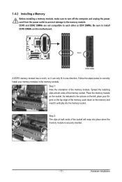
... DIMMs are not compatible to each other or DDR DIMMs. Be sure to install DDR3 DIMMs on the socket. Place the memory module on this motherboard. Step 2: The clips at both ends of the socket will snap into the memory socket. As indicated in one direction. Notch DDR3 DIMM A DDR3 memory...
... DIMMs are not compatible to each other or DDR DIMMs. Be sure to install DDR3 DIMMs on the socket. Place the memory module on this motherboard. Step 2: The clips at both ends of the socket will snap into the memory socket. As indicated in one direction. Notch DDR3 DIMM A DDR3 memory...
Manual
Page 18
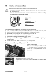
Remove the metal slot cover from the power outlet before you begin to install an expansion card: • Make sure the motherboard supports the expansion card. Secure the card's metal bracket to the chassis back panel with your expansion card in the slot. 3. Locate an expansion slot ...
Remove the metal slot cover from the power outlet before you begin to install an expansion card: • Make sure the motherboard supports the expansion card. Secure the card's metal bracket to the chassis back panel with your expansion card in the slot. 3. Locate an expansion slot ...
Manual
Page 19
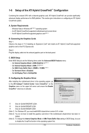
... CrossFireX™ Configuration Combining the onboard GPU with a discrete graphics card, ATI Hybrid CrossFireX can provide significantly advanced display performance for GA-MA785GPMT-UD2H. A. An ATI Hybrid CrossFireX-supported graphics card (Note 2) B. Connecting the Graphics Cards Step 1: Observe the steps in the ... box is selected. Set Internal Graphics Mode to install the graphics card driver if the motherboard chipset driver has been in BIOS Setup, be sure to Disabled. - k Only for GA-MA785GMT-US2H. (Note 1) For Windows XP, you must install AMD chipset driver version ...
... CrossFireX™ Configuration Combining the onboard GPU with a discrete graphics card, ATI Hybrid CrossFireX can provide significantly advanced display performance for GA-MA785GPMT-UD2H. A. An ATI Hybrid CrossFireX-supported graphics card (Note 2) B. Connecting the Graphics Cards Step 1: Observe the steps in the ... box is selected. Set Internal Graphics Mode to install the graphics card driver if the motherboard chipset driver has been in BIOS Setup, be sure to Disabled. - k Only for GA-MA785GMT-US2H. (Note 1) For Windows XP, you must install AMD chipset driver version ...
Manual
Page 21
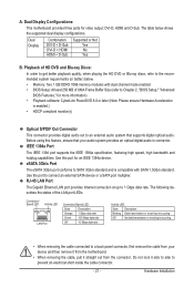
... the IEEE 1394a specification, featuring high speed, high bandwidth and hotplug capabilities. Do not rock it straight out from the motherboard. • When removing the cable, pull it side to side to a back panel connector, first remove the cable ...occurring • When removing the cable connected to prevent an electrical short inside the cable connector. - 21 - Dual Display Configurations: This motherboard provides three ports for more information) • Playback software: CyberLink PowerDVD 8.0 or later (Note: Please ensure Hardware Acceleration is enabled.) ...
... the IEEE 1394a specification, featuring high speed, high bandwidth and hotplug capabilities. Do not rock it straight out from the motherboard. • When removing the cable, pull it side to side to a back panel connector, first remove the cable ...occurring • When removing the cable connected to prevent an electrical short inside the cable connector. - 21 - Dual Display Configurations: This motherboard provides three ports for more information) • Playback software: CyberLink PowerDVD 8.0 or later (Note: Please ensure Hardware Acceleration is enabled.) ...

Manual
Page 23
..., make sure your devices are compliant with the connectors you wish to connect. • Before installing the devices, be sure to the connector on the motherboard. - 23 - Hardware Installation
..., make sure your devices are compliant with the connectors you wish to connect. • Before installing the devices, be sure to the connector on the motherboard. - 23 - Hardware Installation

Manual
Page 24
... a power supply providing a 2x4 12V and a 2x12 power connector, remove the protective covers from the 12V power connector and the main power connector on the motherboard. Before connecting the power connector, first make sure the power supply is used that can withstand high power consumption be used (500W or greater). The... devices are compatible with power supplies with 2x2 12V and 2x10 power connectors. If a power supply is turned off and all the components on the motherboard.
... a power supply providing a 2x4 12V and a 2x12 power connector, remove the protective covers from the 12V power connector and the main power connector on the motherboard. Before connecting the power connector, first make sure the power supply is used that can withstand high power consumption be used (500W or greater). The... devices are compatible with power supplies with 2x2 12V and 2x10 power connectors. If a power supply is turned off and all the components on the motherboard.

Manual
Page 25
... GND 1 2 +12V 3 NC • Be sure to connect fan cables to the fan headers to this header. Hardware Installation The motherboard supports CPU fan speed control, which requires the use of a CPU fan with colorcoded power connector wires. Most fans are designed with fan ...or the system may hang. • These fan headers are designed with color-coded power connector wires. Pin No. 3/4) CPU_FAN/SYS_FAN (Fan Headers) The motherboard has a 4-pin CPU fan header (CPU_FAN)and a 4-pin system fan header(SYS_FAN). A red power connector wire indicates a positive connection and requires a...
... GND 1 2 +12V 3 NC • Be sure to connect fan cables to the fan headers to this header. Hardware Installation The motherboard supports CPU fan speed control, which requires the use of a CPU fan with colorcoded power connector wires. Most fans are designed with fan ...or the system may hang. • These fan headers are designed with color-coded power connector wires. Pin No. 3/4) CPU_FAN/SYS_FAN (Fan Headers) The motherboard has a 4-pin CPU fan header (CPU_FAN)and a 4-pin system fan header(SYS_FAN). A red power connector wire indicates a positive connection and requires a...
Manual
Page 29
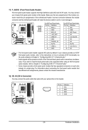
...; Audio signals will make the device unable to the header. Hardware Installation Incorrect connection between the module connector and the motherboard header will be present on each wire instead of the motherboard header. You may connect the audio cable that has separated connectors on both of the front and back panel audio...
...; Audio signals will make the device unable to the header. Hardware Installation Incorrect connection between the module connector and the motherboard header will be present on each wire instead of the motherboard header. You may connect the audio cable that has separated connectors on both of the front and back panel audio...


