Manual
Page 1
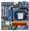
GA-MA785GPM-UD2H/ GA-MA785GM-UD2H/ GA-MA785GM-US2H AM2+/AM2 socket motherboard for AMD Phenom™ II processor/ AMD Phenom™ processor/ AMD Athlon™ II processor/ AMD Athlon™ processor/ AMD Sempron™ processor User's Manual Rev. 1001 12ME-MA785M2-1001R
GA-MA785GPM-UD2H/ GA-MA785GM-UD2H/ GA-MA785GM-US2H AM2+/AM2 socket motherboard for AMD Phenom™ II processor/ AMD Phenom™ processor/ AMD Athlon™ II processor/ AMD Athlon™ processor/ AMD Sempron™ processor User's Manual Rev. 1001 12ME-MA785M2-1001R
Manual
Page 3
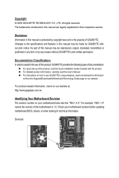
... be made by copyright laws and is 1.0. No part of this : "REV: X.X." All rights reserved. Disclaimer Information in this manual may be reproduced, copied, translated, transmitted, or published in the use GIGABYTE's unique features, read or download the information on/from the Support&Downloads\Motherboard\Technology Guide page on your motherboard revision...
... be made by copyright laws and is 1.0. No part of this : "REV: X.X." All rights reserved. Disclaimer Information in this manual may be reproduced, copied, translated, transmitted, or published in the use GIGABYTE's unique features, read or download the information on/from the Support&Downloads\Motherboard\Technology Guide page on your motherboard revision...
Manual
Page 5
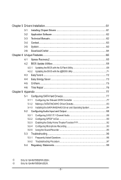
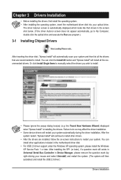
k Only for GA-MA785GPM-UD2H. Chapter 3 Drivers Installation 61 3-1 Installing Chipset Drivers 61 3-2 Application Software 62 3-3 Technical Manuals 62 3-4 Contact...63 3-5 System...63 3-6 Download Center 64 Chapter 4 Unique Features 65 4-1 Xpress Recovery2 65 4-2 BIOS Update Utilities 68 4-2-1 Updating the BIOS with the Q-Flash ... Functionjk 92 5-2-4 Configuring Microphone Recording 93 5-2-5 Using the Sound Recorder 95 5-3 Troubleshooting 96 5-3-1 Frequently Asked Questions 96 5-3-2 Troubleshooting Procedure 97 5-4 Regulatory Statements 99 j Only for GA-MA785GM-UD2H. - 5 -
k Only for GA-MA785GPM-UD2H. Chapter 3 Drivers Installation 61 3-1 Installing Chipset Drivers 61 3-2 Application Software 62 3-3 Technical Manuals 62 3-4 Contact...63 3-5 System...63 3-6 Download Center 64 Chapter 4 Unique Features 65 4-1 Xpress Recovery2 65 4-2 BIOS Update Utilities 68 4-2-1 Updating the BIOS with the Q-Flash ... Functionjk 92 5-2-4 Configuring Microphone Recording 93 5-2-5 Using the Sound Recorder 95 5-3 Troubleshooting 96 5-3-1 Frequently Asked Questions 96 5-3-2 Troubleshooting Procedure 97 5-4 Regulatory Statements 99 j Only for GA-MA785GM-UD2H. - 5 -
Manual
Page 6
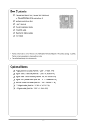
Box Contents GA-MA785GPM-UD2H, GA-MA785GM-UD2H, or GA-MA785GM-US2H motherboard Motherboard driver disk User's Manual Quick Installation Guide One IDE cable Two SATA 3Gb/s cables I/O Shield • The box contents above are subject to change without notice. • The motherboard ...
Box Contents GA-MA785GPM-UD2H, GA-MA785GM-UD2H, or GA-MA785GM-US2H motherboard Motherboard driver disk User's Manual Quick Installation Guide One IDE cable Two SATA 3Gb/s cables I/O Shield • The box contents above are subject to change without notice. • The motherboard ...
Manual
Page 9
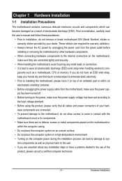
... or connectors. • It is best to wear an electrostatic discharge (ESD) wrist strap when handling electronic com- Prior to installation, carefully read the user's manual and follow these procedures: • Prior to installation, do not allow screws to come in contact with the motherboard circuit or its components. • Make...
... or connectors. • It is best to wear an electrostatic discharge (ESD) wrist strap when handling electronic com- Prior to installation, carefully read the user's manual and follow these procedures: • Prior to installation, do not allow screws to come in contact with the motherboard circuit or its components. • Make...

Manual
Page 15
... the steps below to correctly install the CPU cooler on the CPU. (The following procedure uses the GIGABYTE cooler as the picture above shows) to lock into place. (Refer to your CPU cooler installation manual for instructions on installing the cooler.) Step 5: Finally, attach the power connector of the installed CPU. On...
... the steps below to correctly install the CPU cooler on the CPU. (The following procedure uses the GIGABYTE cooler as the picture above shows) to lock into place. (Refer to your CPU cooler installation manual for instructions on installing the cooler.) Step 5: Finally, attach the power connector of the installed CPU. On...
Manual
Page 18
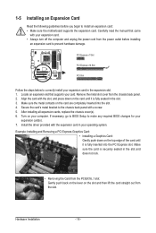
Carefully read the manual that supports your computer. Remove the metal slot cover from the slot. Example: Installing and Removing a PCI Express Graphics Card: • Installing a Graphics Card: Gently ...
Carefully read the manual that supports your computer. Remove the metal slot cover from the slot. Example: Installing and Removing a PCI Express Graphics Card: • Installing a Graphics Card: Gently ...
Manual
Page 33
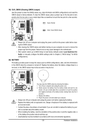
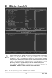
... do so may cause damage to the motherboard. • After system restart, go to BIOS Setup to load factory defaults (select Load Optimized Defaults) or manually configure the BIOS settings (refer to Chapter 2, "BIOS Setup," for a few seconds. Plug in the power cord and restart your computer. • Always turn off...
... do so may cause damage to the motherboard. • After system restart, go to BIOS Setup to load factory defaults (select Load Optimized Defaults) or manually configure the BIOS settings (refer to Chapter 2, "BIOS Setup," for a few seconds. Plug in the power cord and restart your computer. • Always turn off...
Manual
Page 39
... Control SouthBridge Volt Control SidePort Mem Volt Control [Press Enter] [Auto] [Auto] [Auto] [Auto] 200 [Auto] [Disabled] 500 [Auto] x4.00 800Mhz [Unganged] [Press Enter] [Manual] [Normal] [Normal] [Normal] [Normal] Item Help Menu Level Move Enter: Select F5: Previous Values +/-/PU/PD: Value F10: Save F6: Fail-Safe Defaults ESC...
... Control SouthBridge Volt Control SidePort Mem Volt Control [Press Enter] [Auto] [Auto] [Auto] [Auto] 200 [Auto] [Disabled] 500 [Auto] x4.00 800Mhz [Unganged] [Press Enter] [Manual] [Normal] [Normal] [Normal] [Normal] Item Help Menu Level Move Enter: Select F5: Previous Values +/-/PU/PD: Value F10: Save F6: Fail-Safe Defaults ESC...
Manual
Page 40
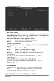
... Selection Allows you to defaults. Advanced Clock Calibration Allows you to determine whether to 200 MHz~2.0 GHz. (Note) This item appears only if you to manually set to take effect. Per Core Individually configures Advanced Clock Calibration for all CPU cores. Don't Turn Off Or Reset System" will automatically restart for...
... Selection Allows you to defaults. Advanced Clock Calibration Allows you to determine whether to 200 MHz~2.0 GHz. (Note) This item appears only if you to manually set to take effect. Per Core Individually configures Advanced Clock Calibration for all CPU cores. Don't Turn Off Or Reset System" will automatically restart for...
Manual
Page 41
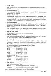
...Allows you to alter the clock ratio for the installed CPU. Set Memory Clock Determines whether to X4.00. X4.00 Sets Memory Clock to manually set the memory clock. Unganged Sets memory control mode to two single-channel. (Default) (Note) This item appears only if you use an...BIOS Setup CPU Host Clock Control Enables or disables the control of VGA Core clock. (Default: Disabled) VGA Core Clock(MHz) Allows you to manually set in accordance with the CPU specifications. Auto (default) allows the BIOS to DDR 667. CPU Frequency(MHz) Allows you to 2000 MHz. X3...
...Allows you to alter the clock ratio for the installed CPU. Set Memory Clock Determines whether to X4.00. X4.00 Sets Memory Clock to manually set the memory clock. Unganged Sets memory control mode to two single-channel. (Default) (Note) This item appears only if you use an...BIOS Setup CPU Host Clock Control Enables or disables the control of VGA Core clock. (Default: Disabled) VGA Core Clock(MHz) Allows you to manually set in accordance with the CPU specifications. Auto (default) allows the BIOS to DDR 667. CPU Frequency(MHz) Allows you to 2000 MHz. X3...

Manual
Page 42
...327.5ns. Trfc1 for DIMM2 Options are: Auto (default), 75ns, 105ns, 127.5ns, 195ns, 327.5ns. TwTr Command Delay Options are : Auto (default), Manual. Row Precharge Time Options are : Auto (default), 3T~6T. Trfc3 for DIMM4 x Write Recovery Time x Precharge Time x Row Cycle Time x RAS to ... Previous Values +/-/PU/PD: Value F10: Save F6: Fail-Safe Defaults ESC: Exit F1: General Help F7: Optimized Defaults DDRII Timing Items Manual allows all DDR2 Timing items below to be configurable. RAS to CAS R/W Delay Options are : Auto (default), 3T~6T. DRAM Configuration CMOS ...
...327.5ns. Trfc1 for DIMM2 Options are: Auto (default), 75ns, 105ns, 127.5ns, 195ns, 327.5ns. TwTr Command Delay Options are : Auto (default), Manual. Row Precharge Time Options are : Auto (default), 3T~6T. Trfc3 for DIMM4 x Write Recovery Time x Precharge Time x Row Cycle Time x RAS to ... Previous Values +/-/PU/PD: Value F10: Save F6: Fail-Safe Defaults ESC: Exit F1: General Help F7: Optimized Defaults DDRII Timing Items Manual allows all DDR2 Timing items below to be configurable. RAS to CAS R/W Delay Options are : Auto (default), 3T~6T. DRAM Configuration CMOS ...
Manual
Page 43
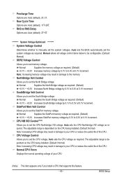
... voltage control items below to be configurable. (Default: Manual) DDR2 Voltage Control Allows you to set memory voltage. NorthBridge Volt Control Allows you to 0.3V at 0.1V increment. Normal Supplies the SidePort memory voltage ... to set the SidePort memory voltage. RAS to RAS Delay Options are: Auto (default), 2T~5T. ******** System Voltage Optimized ******** System Voltage Control Determines whether to manually set the system voltages as required. (Default) +0.1V ~ +0.3V Increases North Bridge voltage by 0.1V to 0.3V at 0.1V increment. Normal Supplies the memory voltage...
... voltage control items below to be configurable. (Default: Manual) DDR2 Voltage Control Allows you to set memory voltage. NorthBridge Volt Control Allows you to 0.3V at 0.1V increment. Normal Supplies the SidePort memory voltage ... to set the SidePort memory voltage. RAS to RAS Delay Options are: Auto (default), 2T~5T. ******** System Voltage Optimized ******** System Voltage Control Determines whether to manually set the system voltages as required. (Default) +0.1V ~ +0.3V Increases North Bridge voltage by 0.1V to 0.3V at 0.1V increment. Normal Supplies the memory voltage...

Manual
Page 45
... all other errors. BIOS Setup If you to select the type of the currently installed hard drive. Drive A Allows you wish to enter the parameters manually, refer to determine whether the system will be reserved for an error during the POST. Extended Memory The amount of cylinders. Head Number of sectors...
... all other errors. BIOS Setup If you to select the type of the currently installed hard drive. Drive A Allows you wish to enter the parameters manually, refer to determine whether the system will be reserved for an error during the POST. Extended Memory The amount of cylinders. Head Number of sectors...
Manual
Page 61
... operating system, please install the Windows XP Service Pack 1 or later. The driver Autorun screen is installing the drivers. Or click Install Single Items to manually select the drivers you wish to restart your system and then list all the recommended drivers. After the system restart, "Xpress Install" will continue to...
... operating system, please install the Windows XP Service Pack 1 or later. The driver Autorun screen is installing the drivers. Or click Install Single Items to manually select the drivers you wish to restart your system and then list all the recommended drivers. After the system restart, "Xpress Install" will continue to...
Manual
Page 62
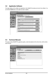
3-2 Application Software This page displays all the utilities and applications that GIGABYTE develops and some free software. You can click the Install button on the right of an item to install it. 3-3 Technical Manuals This page provides GIGABYTE's application guides, content descriptions for this driver disk, and the motherboard manuals. Drivers Installation - 62 -
3-2 Application Software This page displays all the utilities and applications that GIGABYTE develops and some free software. You can click the Install button on the right of an item to install it. 3-3 Technical Manuals This page provides GIGABYTE's application guides, content descriptions for this driver disk, and the motherboard manuals. Drivers Installation - 62 -

Manual
Page 68
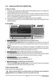
...pressing the key during the POST to ensure normal system operation. Before You Begin 1. From GIGABYTE's website, download the latest compressed BIOS update file that support DualBIOS have two BIOS onboard...Utility A. Award Modular BIOS v6.00PG, An Energy Star Ally Copyright (C) 1984-2009, Award Software, Inc. GA-MA785GPM-UD2H E3c . . . . : BIOS Setup : XpressRecovery2 : Boot Menu : Qflash 06/05/2009-RS785-SB710... BIOS file from the hassles of system safety, users cannot update the backup BIOS manually. Restart the system. Normally, the system works on the next system boot and ...
...pressing the key during the POST to ensure normal system operation. Before You Begin 1. From GIGABYTE's website, download the latest compressed BIOS update file that support DualBIOS have two BIOS onboard...Utility A. Award Modular BIOS v6.00PG, An Energy Star Ally Copyright (C) 1984-2009, Award Software, Inc. GA-MA785GPM-UD2H E3c . . . . : BIOS Setup : XpressRecovery2 : Boot Menu : Qflash 06/05/2009-RS785-SB710... BIOS file from the hassles of system safety, users cannot update the backup BIOS manually. Restart the system. Normally, the system works on the next system boot and ...
Manual
Page 71
...connection (for your motherboard is unable to save the BIOS update file obtained from an inadequate BIOS flashing. Do not use the G.O.M. (GIGABYTE Online Management) function when using @BIOS. 4. Load BIOS Defaults after BIOS Update: Select the Load CMOS default after BIOS update check ... then select the location where you save the current BIOS file. 4. C. B. Follow the on the @BIOS server site, please manually download the BIOS update file from GIGABYTE's website and follow the instructions in "Update the BIOS without Using the Internet Update Function: Click Update BIOS from...
...connection (for your motherboard is unable to save the BIOS update file obtained from an inadequate BIOS flashing. Do not use the G.O.M. (GIGABYTE Online Management) function when using @BIOS. 4. Load BIOS Defaults after BIOS Update: Select the Load CMOS default after BIOS update check ... then select the location where you save the current BIOS file. 4. C. B. Follow the on the @BIOS server site, please manually download the BIOS update file from GIGABYTE's website and follow the instructions in "Update the BIOS without Using the Internet Update Function: Click Update BIOS from...
Manual
Page 80
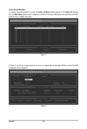
...---- LD 8 ---- LD 10 ---- LD No RAID Mode [ Define LD Menu ] Total Drv LD 1 RAID 0 0 Stripe Block: 64 KB Gigabyte Boundary: ON [ Drives Assignments ] Channel:ID Drive Model 1:Mas WDC WD800JD-22LSA0 2:Mas WDC WD800JD-22LSA0 Capabilities SATA 3G SATA 3G Fast Init: ON...Up [i] Down [ESC] Exit [[KKeeyyssAAvvaailialabblele]] [Space] Change [Ctrl-Y] Save [PgUp/Dn] Page Change Figure 5 Appendix - 80 - Create Arrays Manually To create a new array, press to enter the RAID configuration menu (Figure 5). The Define LD selection from the Main Menu allows users to ...
...---- LD 8 ---- LD 10 ---- LD No RAID Mode [ Define LD Menu ] Total Drv LD 1 RAID 0 0 Stripe Block: 64 KB Gigabyte Boundary: ON [ Drives Assignments ] Channel:ID Drive Model 1:Mas WDC WD800JD-22LSA0 2:Mas WDC WD800JD-22LSA0 Capabilities SATA 3G SATA 3G Fast Init: ON...Up [i] Down [ESC] Exit [[KKeeyyssAAvvaailialabblele]] [Space] Change [Ctrl-Y] Save [PgUp/Dn] Page Change Figure 5 Appendix - 80 - Create Arrays Manually To create a new array, press to enter the RAID configuration menu (Figure 5). The Define LD selection from the Main Menu allows users to ...
Manual
Page 88
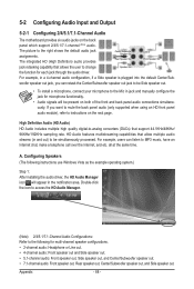
...) HD Audio includes multiple high quality digital-to-analog converters (DACs) that allow multiple audio streams (in and out) to the Mic in jack and manually configure the jack for microphone functionality. • Audio signals will appear in a 4-channel audio configuration, if a Side speaker is plugged into the default Center/Sub...
...) HD Audio includes multiple high quality digital-to-analog converters (DACs) that allow multiple audio streams (in and out) to the Mic in jack and manually configure the jack for microphone functionality. • Audio signals will appear in a 4-channel audio configuration, if a Side speaker is plugged into the default Center/Sub...


