Manual
Page 1
GA-MA69VM-S2 AMD AthlonTM 64 FX / AthlonTM 64 X2 Dual-Core / AMD AthlonTM 64 / SempronTM AM2 Processor Motherboard User's Manual Rev. 1002 12ME-MA69VMS2-1002R * The WEEE marking on the product indicates this product must not be disposed of with user's other household waste and must be handed over to a designated collection point for the recycling of waste electrical and electronic equipment!! * The WEEE marking applies only in European Union's member states.
GA-MA69VM-S2 AMD AthlonTM 64 FX / AthlonTM 64 X2 Dual-Core / AMD AthlonTM 64 / SempronTM AM2 Processor Motherboard User's Manual Rev. 1002 12ME-MA69VMS2-1002R * The WEEE marking on the product indicates this product must not be disposed of with user's other household waste and must be handed over to a designated collection point for the recycling of waste electrical and electronic equipment!! * The WEEE marking applies only in European Union's member states.
Manual
Page 4
Table of Contents ItemChecklist ...6 OptionalAccessories ...6 GA-MA69VM-S2 Motherboard Layout 7 Block Diagram ...8 Chapter 1 Hardware Installation 9 1-1 Considerations Prior to Installation 9 1-2 Feature Summary 10 1-3 Installation of the CPU and CPU Cooler 12 1-3-1 Installation of the CPU ...
Table of Contents ItemChecklist ...6 OptionalAccessories ...6 GA-MA69VM-S2 Motherboard Layout 7 Block Diagram ...8 Chapter 1 Hardware Installation 9 1-1 Considerations Prior to Installation 9 1-2 Feature Summary 10 1-3 Installation of the CPU and CPU Cooler 12 1-3-1 Installation of the CPU ...
Manual
Page 7
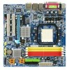
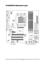
ATX GA-MA69VM-S2 Motherboard Layout MS / KB ATX_12V COMA Socket AM2 LPT VGA CPU_FAN USB USB LAN TV AUDIO IT8716 CI BIOS PCIE_4 GA-MA69VM-S2 AMD 690V F_AUDIO RTL8110SC PCIE_16 PCI1 PCI2 CODEC COMB CD_IN SPDIF_IO DDRII1 DDRII2 DDRII3 DDRII4 IDE SATAII2 SATAII0 AMD SB600 SYS_FAN SATAII3 BATTERY SATAII1 CLR_CMOS F_PANEL F_USB1 F_USB2 F_USB3 PWR_LED FDD - 7 -
ATX GA-MA69VM-S2 Motherboard Layout MS / KB ATX_12V COMA Socket AM2 LPT VGA CPU_FAN USB USB LAN TV AUDIO IT8716 CI BIOS PCIE_4 GA-MA69VM-S2 AMD 690V F_AUDIO RTL8110SC PCIE_16 PCI1 PCI2 CODEC COMB CD_IN SPDIF_IO DDRII1 DDRII2 DDRII3 DDRII4 IDE SATAII2 SATAII0 AMD SB600 SYS_FAN SATAII3 BATTERY SATAII1 CLR_CMOS F_PANEL F_USB1 F_USB2 F_USB3 PWR_LED FDD - 7 -
Manual
Page 9
... as well as physical harm to the user. 8. Damage due to be an unofficial Gigabyte product. - 9 - Please turn off before unplugging the power supply connector from the motherboard. Instances of an antistatic pad or within the computer casing. 6. Damage as a result... 5. Damage due to installing the electronic components, please have a problem related to use of electrostatic discharge (ESD). When handling the motherboard, avoid touching any installation steps or have these items on an uneven surface. 7. Product determined to improper installation. 4. If you ...
... as well as physical harm to the user. 8. Damage due to be an unofficial Gigabyte product. - 9 - Please turn off before unplugging the power supply connector from the motherboard. Instances of an antistatic pad or within the computer casing. 6. Damage as a result... 5. Damage due to installing the electronic components, please have a problem related to use of electrostatic discharge (ESD). When handling the motherboard, avoid touching any installation steps or have these items on an uneven surface. 7. Product determined to improper installation. 4. If you ...
Manual
Page 10
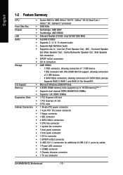
... CPU Š Socket AM2 for additional 6 USB 2.0/1.1 ports by cables Š 1 Power LED connector Š 1 COMB connector Š 1 Chassis Intrusion connector Š 1 TV out connector GA-MA69VM-S2 Motherboard - 10 - Supports RAID 0, RAID 1,and RAID 0+1for Serial ATA O.S Support Š Microsoft Windows 2000/XP/Vista Memory Š 4 DDRII DIMM memory slots (supports up to...
... CPU Š Socket AM2 for additional 6 USB 2.0/1.1 ports by cables Š 1 Power LED connector Š 1 COMB connector Š 1 Chassis Intrusion connector Š 1 TV out connector GA-MA69VM-S2 Motherboard - 10 - Supports RAID 0, RAID 1,and RAID 0+1for Serial ATA O.S Support Š Microsoft Windows 2000/XP/Vista Memory Š 4 DDRII DIMM memory slots (supports up to...

Manual
Page 11
... is installed, the actual memory available for the operating system will depend on the CPU you install. (Note 3) EasyTune functions may vary depending on different motherboards. - 11 -
... is installed, the actual memory available for the operating system will depend on the CPU you install. (Note 3) EasyTune functions may vary depending on different motherboards. - 11 -
Manual
Page 12
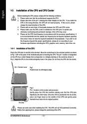
... overheating and permanent damage of the CPU may occur. 5. If you install the CPU in accordance with the following conditions: 1. GA-MA69VM-S2 Motherboard - 12 - Please make sure the CPU cooler is positioned into its original position. Please set beyond the proper specifications, please do... so according to your hardware specifications including the CPU, graphics card, memory, hard drive, etc. 1-3-1 Installation of the motherboard) prior to the socket and gently lower it does not meet the required standards for the peripherals. Pin One Fig.2 Pin ...
... overheating and permanent damage of the CPU may occur. 5. If you install the CPU in accordance with the following conditions: 1. GA-MA69VM-S2 Motherboard - 12 - Please make sure the CPU cooler is positioned into its original position. Please set beyond the proper specifications, please do... so according to your hardware specifications including the CPU, graphics card, memory, hard drive, etc. 1-3-1 Installation of the motherboard) prior to the socket and gently lower it does not meet the required standards for the peripherals. Pin One Fig.2 Pin ...
Manual
Page 13
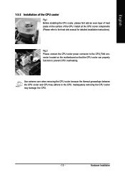
... CPU. - 13 - English 1-3-2 Installation of the CPU cooler Fig.1 Before installing the CPU cooler, please first add an even layer of heat paste on the motherboard so that the CPU cooler can properly function to prevent CPU overheating. Inadequately removing the CPU cooler may adhere to the heat sink manual for...
... CPU. - 13 - English 1-3-2 Installation of the CPU cooler Fig.1 Before installing the CPU cooler, please first add an even layer of heat paste on the motherboard so that the CPU cooler can properly function to prevent CPU overheating. Inadequately removing the CPU cooler may adhere to the heat sink manual for...
Manual
Page 14
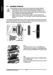
... edges of Memory Before installing the memory modules, please comply with each slot. GA-MA69VM-S2 Motherboard - 14 - Insert the DIMM memory module vertically into the DIMM socket. English 1-4 Installation of the DIMM sockets to remove the DIMM module. The motherboard supports DDRII memory modules, whereby BIOS will automatically detect memory capacity and specifications. Please...
... edges of Memory Before installing the memory modules, please comply with each slot. GA-MA69VM-S2 Motherboard - 14 - Insert the DIMM memory module vertically into the DIMM socket. English 1-4 Installation of the DIMM sockets to remove the DIMM module. The motherboard supports DDRII memory modules, whereby BIOS will automatically detect memory capacity and specifications. Please...
Manual
Page 16
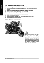
... press firmly down on the card are indeed seated in motherboard. 4. Install related driver from BIOS. 8. Press the expansion card firmly into the computer. 2. Installing a PCI Express x16 expansion card: Please carefully pull out the small whitedrawable bar at the end of the expansion card. 6. Remove your computer's chassis cover. 7. GA-MA69VM-S2 Motherboard - 16 -
... press firmly down on the card are indeed seated in motherboard. 4. Install related driver from BIOS. 8. Press the expansion card firmly into the computer. 2. Installing a PCI Express x16 expansion card: Please carefully pull out the small whitedrawable bar at the end of the expansion card. 6. Remove your computer's chassis cover. 7. GA-MA69VM-S2 Motherboard - 16 -
Manual
Page 18
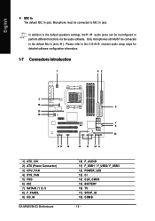
... configuration information. 1-7 Connectors Introduction 1 62 3 16 5 13 10 7 4 14 9 17 18 15 11 12 8 1) ATX_12V 2) ATX (Power Connector) 3) CPU_FAN 4) SYS_FAN 5) FDD 6) IDE 7) SATAII0 /1 /2 /3 8) F_PANEL 9) CD_IN GA-MA69VM-S2 Motherboard 10) F_AUDIO 11) F_USB1 / F_USB2/ F_USB3 12) POWER_LED 13) CI 14) CLR_CMOS 15) BATTERY 16) TV 17) SPDIF_IO 18) COMB - 18 - English MIC In The...
... configuration information. 1-7 Connectors Introduction 1 62 3 16 5 13 10 7 4 14 9 17 18 15 11 12 8 1) ATX_12V 2) ATX (Power Connector) 3) CPU_FAN 4) SYS_FAN 5) FDD 6) IDE 7) SATAII0 /1 /2 /3 8) F_PANEL 9) CD_IN GA-MA69VM-S2 Motherboard 10) F_AUDIO 11) F_USB1 / F_USB2/ F_USB3 12) POWER_LED 13) CI 14) CLR_CMOS 15) BATTERY 16) TV 17) SPDIF_IO 18) COMB - 18 - English MIC In The...
Manual
Page 19
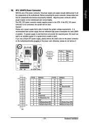
..., the result can supply enough stable power to all components and devices are properly installed. Align the power connector with its proper location on the motherboard before plugging in the power cord; If a power supply is used (300W or greater). otherwise, please do not remove it. 2 1 4 3 ATX_12V ... the CPU. If you use a 24-pin ATX power supply, please remove the small cover on the power connector on the motherboard and connect tightly. The ATX_12V power connector mainly supplies power to handle the system voltage requirements. English 1/2) ATX_12V/ATX (Power Connector...
..., the result can supply enough stable power to all components and devices are properly installed. Align the power connector with its proper location on the motherboard before plugging in the power cord; If a power supply is used (300W or greater). otherwise, please do not remove it. 2 1 4 3 ATX_12V ... the CPU. If you use a 24-pin ATX power supply, please remove the small cover on the power connector on the motherboard and connect tightly. The ATX_12V power connector mainly supplies power to handle the system voltage requirements. English 1/2) ATX_12V/ATX (Power Connector...
Manual
Page 20
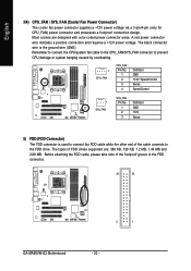
... via a 3-pin/4-pin (only for CPU_FAN) power connector and possesses a foolproof connection design. The types of the foolproof groove in the FDD connector. 34 33 2 1 GA-MA69VM-S2 Motherboard - 20 - A red power connector wire indicates a positive connection and requires a +12V power voltage. The black connector wire is used to connect the FDD cable while...
... via a 3-pin/4-pin (only for CPU_FAN) power connector and possesses a foolproof connection design. The types of the foolproof groove in the FDD connector. 34 33 2 1 GA-MA69VM-S2 Motherboard - 20 - A red power connector wire indicates a positive connection and requires a +12V power voltage. The black connector wire is used to connect the FDD cable while...
Manual
Page 22
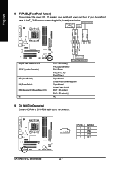
...(-) NC 9) CD_IN (CD In Connector) Connect CD-ROM or DVD-ROM audio out to the pin assignment below. Pin No. Definition 1 CD-L 1 2 GND 3 GND 4 CD-R GA-MA69VM-S2 Motherboard - 22 - Message LED/ Power/ Sleep LED Speaker Connector Power Switch MSG+ MSG-
...(-) NC 9) CD_IN (CD In Connector) Connect CD-ROM or DVD-ROM audio out to the pin assignment below. Pin No. Definition 1 CD-L 1 2 GND 3 GND 4 CD-R GA-MA69VM-S2 Motherboard - 22 - Message LED/ Power/ Sleep LED Speaker Connector Power Switch MSG+ MSG-
Manual
Page 24
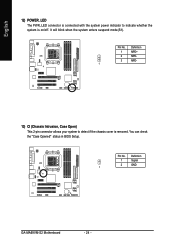
Definition 1 MPD+ 2 MPD- 3 MPD- 1 13) CI (Chassis Intrusion, Case Open) This 2-pin connector allows your system to indicate whether the system is removed. Pin No. Definition 1 Signal 2 GND 1 GA-MA69VM-S2 Motherboard - 24 - Pin No. It will blink when the system enters suspend mode(S1). You can check the "Case Opened" status in BIOS Setup. English 12) POWER_LED The PWR_LED connector is connected with the system power indicator to detect if the chassis cover is on/off.
Definition 1 MPD+ 2 MPD- 3 MPD- 1 13) CI (Chassis Intrusion, Case Open) This 2-pin connector allows your system to indicate whether the system is removed. Pin No. Definition 1 Signal 2 GND 1 GA-MA69VM-S2 Motherboard - 24 - Pin No. It will blink when the system enters suspend mode(S1). You can check the "Case Opened" status in BIOS Setup. English 12) POWER_LED The PWR_LED connector is connected with the system power indicator to detect if the chassis cover is on/off.
Manual
Page 26
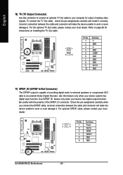
... your computer for output of the SPDIF_IO connector. For optional S/PDIF cable, please contact your local dealer. Definition 5 1 6 2 1 Power 2 No Pin 3 SPDIF 4 SPDIFI 5 GND 6 GND GA-MA69VM-S2 Motherboard - 26 - To connect the TV Out cable, check the pin assignments carefully and install it . For the optional TV Out cable, please contact your local...
... your computer for output of the SPDIF_IO connector. For optional S/PDIF cable, please contact your local dealer. Definition 5 1 6 2 1 Power 2 No Pin 3 SPDIF 4 SPDIFI 5 GND 6 GND GA-MA69VM-S2 Motherboard - 26 - To connect the TV Out cable, check the pin assignments carefully and install it . For the optional TV Out cable, please contact your local...
Manual
Page 29
... require users to boot to quickly and easily update or backup BIOS without entering the operating system. @BIOS is displayed at the bottom of the motherboard. Q-Flash allows the user to DOS before upgrading BIOS but directly download and update BIOS from BIOS default table Load the Optimized Defaults Q-Flash utility... settings or to select item Select Item Main Menu - The CMOS SETUP saves the configuration in system malfunction. - 29 - If you to a new BIOS, either GIGABYTE's Q-Flash or @BIOS utility can enter the BIOS setup screen by pressing "Ctrl + F1".
... require users to boot to quickly and easily update or backup BIOS without entering the operating system. @BIOS is displayed at the bottom of the motherboard. Q-Flash allows the user to DOS before upgrading BIOS but directly download and update BIOS from BIOS default table Load the Optimized Defaults Q-Flash utility... settings or to select item Select Item Main Menu - The CMOS SETUP saves the configuration in system malfunction. - 29 - If you to a new BIOS, either GIGABYTE's Q-Flash or @BIOS utility can enter the BIOS setup screen by pressing "Ctrl + F1".
Manual
Page 30
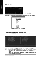
...the settings you enter Award BIOS CMOS Setup Utility, the Main Menu (as usual. Select the Load Optimized Defaults item in this menu. GA-MA69VM-S2 Motherboard - 30 - The BIOS Setup menus described in the BIOS Setup when somehow the system is not stable as figure below) will appear... options. 2. English : Boot Menu Select boot sequence for onboard (or add-on the screen. This action makes the system reset to the default settings for GA-MA69VM-S2 D11 . . . . :BIOS Setup/Q-Flash :Xpress Recovery2 :Boot Menu :Qflash 02/14/2007-RS690V-SB600-6A669G01C-00 : Boot Menu Use < > or < >...
...the settings you enter Award BIOS CMOS Setup Utility, the Main Menu (as usual. Select the Load Optimized Defaults item in this menu. GA-MA69VM-S2 Motherboard - 30 - The BIOS Setup menus described in the BIOS Setup when somehow the system is not stable as figure below) will appear... options. 2. English : Boot Menu Select boot sequence for onboard (or add-on the screen. This action makes the system reset to the default settings for GA-MA69VM-S2 D11 . . . . :BIOS Setup/Q-Flash :Xpress Recovery2 :Boot Menu :Qflash 02/14/2007-RS690V-SB600-6A669G01C-00 : Boot Menu Use < > or < >...
Manual
Page 32
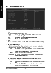
For example, 1 p.m. Access Mode Use this option for the hard drive. GA-MA69VM-S2 Motherboard - 32 - English 2-1 Standard CMOS Features Date (mm:dd:yy) Time (hh:mm:ss) CMOS Setup Utility-Copyright (C) 1984-2007 Award Software Standard CMOS Features Wed, ...
For example, 1 p.m. Access Mode Use this option for the hard drive. GA-MA69VM-S2 Motherboard - 32 - English 2-1 Standard CMOS Features Date (mm:dd:yy) Time (hh:mm:ss) CMOS Setup Utility-Copyright (C) 1984-2007 Award Software Standard CMOS Features Wed, ...
Manual
Page 33
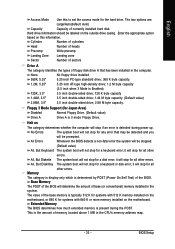
...for a keyboard or disk error; Halt on the outside drive casing. This is present during power up. Enter the appropriate option based on the motherboard. it will not stop for Japan Area) Disabled Normal Floppy Drive. (Default value) Drive A Drive A is typically 512 K for systems with...Setup it will be prompted. English Access Mode Use this to set the access mode for systems with 512 K memory installed on the motherboard, or 640 K for the hard drive. All Errors Whenever the BIOS detects a non-fatal error the system will stop for all other...
...for a keyboard or disk error; Halt on the outside drive casing. This is present during power up. Enter the appropriate option based on the motherboard. it will not stop for Japan Area) Disabled Normal Floppy Drive. (Default value) Drive A Drive A is typically 512 K for systems with...Setup it will be prompted. English Access Mode Use this to set the access mode for systems with 512 K memory installed on the motherboard, or 640 K for the hard drive. All Errors Whenever the BIOS detects a non-fatal error the system will stop for all other...


