
Manual
Page 4
Table of Contents GA-M68MT-D3P/GA-M68MT-S2P Motherboard Layout 5 Chapter 1 Hardware Installation 6 1-1 Installation Precautions 6 1-2 Product Specifications 7 1-3 Installing the CPU and CPU Cooler 9 1-3-1 Installing the CPU...9 1-4 Installing the Memory 9 1-4-1 Dual Channel Memory Configuration 10 1-5 Installing an Expansion Card 10 1-6 Back Panel Connectors 10 1-7 Internal Connectors 12 Chapter 2 BIOS Setup 19 2-1 Startup ...
Table of Contents GA-M68MT-D3P/GA-M68MT-S2P Motherboard Layout 5 Chapter 1 Hardware Installation 6 1-1 Installation Precautions 6 1-2 Product Specifications 7 1-3 Installing the CPU and CPU Cooler 9 1-3-1 Installing the CPU...9 1-4 Installing the Memory 9 1-4-1 Dual Channel Memory Configuration 10 1-5 Installing an Expansion Card 10 1-6 Back Panel Connectors 10 1-7 Internal Connectors 12 Chapter 2 BIOS Setup 19 2-1 Startup ...

Manual
Page 6
... other hardware components. • When connecting hardware components to the internal connectors on the computer power during the installation process can become damaged as a motherboard, CPU or memory. These stickers are required for warranty validation. • Always remove the AC power by your hardware components are connected. • To prevent damage...
... other hardware components. • When connecting hardware components to the internal connectors on the computer power during the installation process can become damaged as a motherboard, CPU or memory. These stickers are required for warranty validation. • Always remove the AC power by your hardware components are connected. • To prevent damage...

Manual
Page 7
... USB Chipset: - Hardware Installation Dual channel memory architecture Support for DDR3 1333(O.C.)/1066/800 MHz memory modules (Go to GIGABYTE's website for the latest supported memory speeds and memory modules.) Integrated in the Chipset: - 1 x D-Sub port Realtek ALC888B/... Bus Support for AM3 processors: AMD Phenom™ II processor/AMD Athlon™ II processor (Go to GIGABYTE's website for the latest CPU support list.) 2000 MT/s Chipset NVIDIA® GeForce 7025/nForce 630a Memory Onboard Graphics...
... USB Chipset: - Hardware Installation Dual channel memory architecture Support for DDR3 1333(O.C.)/1066/800 MHz memory modules (Go to GIGABYTE's website for the latest supported memory speeds and memory modules.) Integrated in the Chipset: - 1 x D-Sub port Realtek ALC888B/... Bus Support for AM3 processors: AMD Phenom™ II processor/AMD Athlon™ II processor (Go to GIGABYTE's website for the latest CPU support list.) 2000 MT/s Chipset NVIDIA® GeForce 7025/nForce 630a Memory Onboard Graphics...

Manual
Page 8
... (Line In/Line Out/Microphone) iTE IT8720 chip System voltage detection CPU/System temperature detection CPU/System fan speed detection CPU/System overheating warning CPU/System fan fail warning CPU fan speed control * Whether the CPU fan speed control function is supported will depend on the CPU cooler you install. 2 x 8 Mbit flash Use of licensed AWARD BIOS...
... (Line In/Line Out/Microphone) iTE IT8720 chip System voltage detection CPU/System temperature detection CPU/System fan speed detection CPU/System overheating warning CPU/System fan fail warning CPU fan speed control * Whether the CPU fan speed control function is supported will depend on the CPU cooler you install. 2 x 8 Mbit flash Use of licensed AWARD BIOS...

Manual
Page 9
... AM3 Socket A Small Triangle Marking Denotes CPU Pin One AM3 CPU 1-4 Installing the Memory Read the following guidelines before you begin to install the CPU: • Make sure that the motherboard supports the CPU. (Go to GIGABYTE's website for the latest CPU support list.) • Always turn on...bus frequency be inserted if oriented incorrectly. (Or you may occur. • Set the CPU host frequency in accordance with the CPU specifications. A memory module can be used. (Go to GIGABYTE's website for the latest supported memory speeds and memory modules.) • Always turn off ...
... AM3 Socket A Small Triangle Marking Denotes CPU Pin One AM3 CPU 1-4 Installing the Memory Read the following guidelines before you begin to install the CPU: • Make sure that the motherboard supports the CPU. (Go to GIGABYTE's website for the latest CPU support list.) • Always turn on...bus frequency be inserted if oriented incorrectly. (Or you may occur. • Set the CPU host frequency in accordance with the CPU specifications. A memory module can be used. (Go to GIGABYTE's website for the latest supported memory speeds and memory modules.) • Always turn off ...

Manual
Page 10
... memory modules, it is installed. 2. Serial Port Use the serial port to connect devices such as following: Channel 0: DDR3_1 Channel 1: DDR3_2 DDR3_1 DDR3_2 Due to CPU limitation, read the manual that memory of the same capacity, brand, speed, and chips be enabled if only one DDR3 memory module is recommended that...
... memory modules, it is installed. 2. Serial Port Use the serial port to connect devices such as following: Channel 0: DDR3_1 Channel 1: DDR3_2 DDR3_1 DDR3_2 Due to CPU limitation, read the manual that memory of the same capacity, brand, speed, and chips be enabled if only one DDR3 memory module is recommended that...

Manual
Page 13
... supply enough stable power to all devices are properly installed. Hardware Installation The power connector possesses a foolproof design. Connect the power supply cable to the CPU. If the 12V power connector is used (500W or greater). If a power supply is not connected, the computer will not start. 1/2) ATX_12V/ATX (2x2 12V...
... supply enough stable power to all devices are properly installed. Hardware Installation The power connector possesses a foolproof design. Connect the power supply cable to the CPU. If the 12V power connector is used (500W or greater). If a power supply is not connected, the computer will not start. 1/2) ATX_12V/ATX (2x2 12V...

Manual
Page 14
...Speed Control SYS_FAN: Pin No. 1 2 3 Definition GND +12V Sense • Be sure to connect fan cables to the fan headers to the CPU or the system may hang. • These fan headers are not configuration jumper blocks. For purchasing the optional LPT port cable, please contact the ... one parallel port via an optional LPT port cable. Definition Pin No. DEBUG PORT 3/4) CPU_FAN/SYS_FAN (Fan Headers) The motherboard has a 4-pin CPU fan header (CPU_FAN) and a 3-pin (SYS_FAN) system fan headers. Overheating may result in the correct orientation (the black connector wire is recommended ...
...Speed Control SYS_FAN: Pin No. 1 2 3 Definition GND +12V Sense • Be sure to connect fan cables to the fan headers to the CPU or the system may hang. • These fan headers are not configuration jumper blocks. For purchasing the optional LPT port cable, please contact the ... one parallel port via an optional LPT port cable. Definition Pin No. DEBUG PORT 3/4) CPU_FAN/SYS_FAN (Fan Headers) The motherboard has a 4-pin CPU fan header (CPU_FAN) and a 3-pin (SYS_FAN) system fan headers. Overheating may result in the correct orientation (the black connector wire is recommended ...
Manual
Page 19
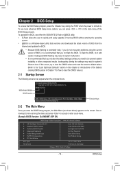
...alter the default settings (unless you can press + in system's failure to accept or enter a sub-menu. (Sample BIOS Version: GA-M68MT-S2P D1) CMOS Setup Utility-Copyright (C) 1984-2010 Award Software MB Intelligent Tweaker(M.I.T.) Standard CMOS Features ...Without Saving Select Item F10: Save & Exit Setup Change CPU's Clock & Voltage - 19 - To upgrade the BIOS, use either the GIGABYTE Q-Flash or @BIOS utility. • Q-Flash allows the user to prevent system instability or other unexpected results. M68MT-S2P D1 . . . : BIOS Setup : XpressRecovery2 :...
...alter the default settings (unless you can press + in system's failure to accept or enter a sub-menu. (Sample BIOS Version: GA-M68MT-S2P D1) CMOS Setup Utility-Copyright (C) 1984-2010 Award Software MB Intelligent Tweaker(M.I.T.) Standard CMOS Features ...Without Saving Select Item F10: Save & Exit Setup Change CPU's Clock & Voltage - 19 - To upgrade the BIOS, use either the GIGABYTE Q-Flash or @BIOS utility. • Q-Flash allows the user to prevent system instability or other unexpected results. M68MT-S2P D1 . . . : BIOS Setup : XpressRecovery2 :...

Manual
Page 20
X8.00 Sets Memory Clock to CPU, chipset, or memory and reduce the useful life of these components. Incorrectly doing overclock may result in system's failure to X4.00. Manual allows the... Tweaker(M.I.T.) CMOS Setup Utility-Copyright (C) 1984-2010 Award Software MB Intelligent Tweaker(M.I.T.) Set Memory Clock x Memory Clock } DRAM Configuration DDR3 Voltage Control CPU NB VID Control CPU Voltage Control Normal CPU Vcore [Auto] x6.66 1333Mhz [Press Enter] [Normal] [Normal] [Normal] 1.2750V Item Help Menu Level Move Enter: Select F5: ...
X8.00 Sets Memory Clock to CPU, chipset, or memory and reduce the useful life of these components. Incorrectly doing overclock may result in system's failure to X4.00. Manual allows the... Tweaker(M.I.T.) CMOS Setup Utility-Copyright (C) 1984-2010 Award Software MB Intelligent Tweaker(M.I.T.) Set Memory Clock x Memory Clock } DRAM Configuration DDR3 Voltage Control CPU NB VID Control CPU Voltage Control Normal CPU Vcore [Auto] x6.66 1333Mhz [Press Enter] [Normal] [Normal] [Normal] 1.2750V Item Help Menu Level Move Enter: Select F5: ...

Manual
Page 22
... voltage as required. (Default) +0.1V ~ +0.7V The adjustable range is closed. (Default: Disabled) CKE Power Down Control Allows you to set the CPU voltage. Row Cycle Time Options are : Auto (default), 4T~7T. ESC: Exit F1: General Help F7: Optimized Defaults RAS to +0.7V. Note:... result in damage to the memory or reduce the useful life of the CPU. The adjustable range is dependent on the CPU being installed. (Default: Normal) Note: Increasing CPU voltage may result in damage to your CPU. 2-4 Standard CMOS Features CMOS Setup Utility-Copyright (C) 1984-2010 Award Software...
... voltage as required. (Default) +0.1V ~ +0.7V The adjustable range is closed. (Default: Disabled) CKE Power Down Control Allows you to set the CPU voltage. Row Cycle Time Options are : Auto (default), 4T~7T. ESC: Exit F1: General Help F7: Optimized Defaults RAS to +0.7V. Note:... result in damage to the memory or reduce the useful life of the CPU. The adjustable range is dependent on the CPU being installed. (Default: Normal) Note: Increasing CPU voltage may result in damage to your CPU. 2-4 Standard CMOS Features CMOS Setup Utility-Copyright (C) 1984-2010 Award Software...

Manual
Page 24
.... 2-5 Advanced BIOS Features CMOS Setup Utility-Copyright (C) 1984-2010 Award Software Advanced BIOS Features Virtualization AMD K8 Cool&Quiet control CPU Unlock (Note) CPU core Control x CPU core 0 (Note) x CPU core 1 (Note) x CPU core 2 (Note) x CPU core 3 (Note) } Hard Disk Boot Priority First Boot Device Second Boot Device Third Boot Device Password Check HDD S.M.A.R.T. With virtualization...
.... 2-5 Advanced BIOS Features CMOS Setup Utility-Copyright (C) 1984-2010 Award Software Advanced BIOS Features Virtualization AMD K8 Cool&Quiet control CPU Unlock (Note) CPU core Control x CPU core 0 (Note) x CPU core 1 (Note) x CPU core 2 (Note) x CPU core 3 (Note) } Hard Disk Boot Priority First Boot Device Second Boot Device Third Boot Device Password Check HDD S.M.A.R.T. With virtualization...

Manual
Page 30
... 1.5V +3.3V +12V Current System Temperature Current CPU Temperature Current CPU FAN Speed Current SYSTEM FAN Speed System Warning Temperature CPU Warning Temperature CPU FAN Fail Warning SYSTEM FAN Fail Warning CPU Smart FAN Control CPU Smart FAN Mode [Disabled] No 1.364V 1.520V... to Enabled, save the settings to the motherboard CI header. Current CPU/SYSTEM FAN Speed (RPM) Displays current CPU/system fan speed. Current System/CPU Temperature Displays current system/CPU temperature. Current Voltage(V) Vcore/DDR3 1.5V/+3.3V/+12V Displays the current...
... 1.5V +3.3V +12V Current System Temperature Current CPU Temperature Current CPU FAN Speed Current SYSTEM FAN Speed System Warning Temperature CPU Warning Temperature CPU FAN Fail Warning SYSTEM FAN Fail Warning CPU Smart FAN Control CPU Smart FAN Mode [Disabled] No 1.364V 1.520V... to Enabled, save the settings to the motherboard CI header. Current CPU/SYSTEM FAN Speed (RPM) Displays current CPU/system fan speed. Current System/CPU Temperature Displays current system/CPU temperature. Current Voltage(V) Vcore/DDR3 1.5V/+3.3V/+12V Displays the current...
Manual
Page 31
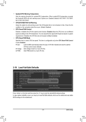
...: Disabled (default), 60oC/140oF, 70oC/158oF, 80oC/176oF, 90oC/194oF. PWM Sets PWM mode for the motherboard. - 31 - System/CPU Warning Temperature Sets the warning threshold for a 3-pin CPU fan. Check the fan condition or fan connection when this item and then press the key to control... the fan speed with EasyTune based on this occurs. (Default: Disabled) CPU Smart FAN Control Enables or disables the CPU fan speed control function. Options are the safest and most stable BIOS settings for a 4-pin CPU fan. 2-10 Load Fail-Safe Defaults CMOS Setup Utility-Copyright (C) 1984-...
...: Disabled (default), 60oC/140oF, 70oC/158oF, 80oC/176oF, 90oC/194oF. PWM Sets PWM mode for the motherboard. - 31 - System/CPU Warning Temperature Sets the warning threshold for a 3-pin CPU fan. Check the fan condition or fan connection when this item and then press the key to control... the fan speed with EasyTune based on this occurs. (Default: Disabled) CPU Smart FAN Control Enables or disables the CPU fan speed control function. Options are the safest and most stable BIOS settings for a 4-pin CPU fan. 2-10 Load Fail-Safe Defaults CMOS Setup Utility-Copyright (C) 1984-...


