Manual
Page 1
GA-M61SME-S2 AMD AthlonTM 64 FX / AthlonTM 64 X2 Dual-Core / AMD AthlonTM 64 / SempronTM AM2 Processor Motherboard User's Manual Rev. 2002 12ME-M61SMES2-2002R
GA-M61SME-S2 AMD AthlonTM 64 FX / AthlonTM 64 X2 Dual-Core / AMD AthlonTM 64 / SempronTM AM2 Processor Motherboard User's Manual Rev. 2002 12ME-M61SMES2-2002R
Manual
Page 2
Motherboard GA-M61SME-S2 Mar. 7, 2007 Motherboard GA-M61SME-S2 Mar. 7, 2007
Motherboard GA-M61SME-S2 Mar. 7, 2007 Motherboard GA-M61SME-S2 Mar. 7, 2007
Manual
Page 4
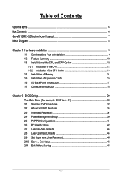
Table of Contents OptionalItems ...6 Box Contents ...6 GA-M61SME-S2 Motherboard Layout 7 Block Diagram ...8 Chapter 1 Hardware Installation 9 1-1 Considerations Prior to Installation 9 1-2 Feature Summary 10 1-3 Installation of the CPU and CPU Cooler 12 1-3-1 Installation of the CPU ...
Table of Contents OptionalItems ...6 Box Contents ...6 GA-M61SME-S2 Motherboard Layout 7 Block Diagram ...8 Chapter 1 Hardware Installation 9 1-1 Considerations Prior to Installation 9 1-2 Feature Summary 10 1-3 Installation of the CPU and CPU Cooler 12 1-3-1 Installation of the CPU ...
Manual
Page 6
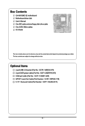
... cable (Part No. 12CF1-1CM001-32R) S/PDIF In and Out Cable (Part Number: 12CR1-1SPINO-11R) 5.1/7.1 Surround Cable (Part Number: 12CF1-1AU004-01R ) - 6 - Box Contents GA-M61SME-S2 motherboard Motherboard driver disk User's Manual One IDE cable and one floppy disk drive cable One SATA 3Gb/s cables I/O Shield The box contents above are subject to...
... cable (Part No. 12CF1-1CM001-32R) S/PDIF In and Out Cable (Part Number: 12CR1-1SPINO-11R) 5.1/7.1 Surround Cable (Part Number: 12CF1-1AU004-01R ) - 6 - Box Contents GA-M61SME-S2 motherboard Motherboard driver disk User's Manual One IDE cable and one floppy disk drive cable One SATA 3Gb/s cables I/O Shield The box contents above are subject to...

Manual
Page 9
... to installation, please follow the instructions below: 1. Chapter 1 Hardware Installation 1-1 Considerations Prior to Installation Preparing Your Computer The motherboard contains numerous delicate electronic circuits and components which can lead to damage to system components as well as physical harm to the user... 8. Thus, prior to be an unofficial Gigabyte product. - 9 - Before using the product, please verify that the power supply is best to installation, please do not place the computer system on the motherboard. Please make sure there are required for warranty...
... to installation, please follow the instructions below: 1. Chapter 1 Hardware Installation 1-1 Considerations Prior to Installation Preparing Your Computer The motherboard contains numerous delicate electronic circuits and components which can lead to damage to system components as well as physical harm to the user... 8. Thus, prior to be an unofficial Gigabyte product. - 9 - Before using the product, please verify that the power supply is best to installation, please do not place the computer system on the motherboard. Please make sure there are required for warranty...
Manual
Page 10
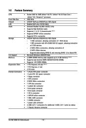
... - 2 SATA 3Gb/s connectors, allowing connection of 2 SATA 3Gb/s devices - 1-2 Feature Summary CPU Š Socket AM2 for additional 4 USB 2.0/1.1 ports by cables Š 1 Chassis Intrusion connector GA-M61SME-S2 Motherboard - 10 -
... - 2 SATA 3Gb/s connectors, allowing connection of 2 SATA 3Gb/s devices - 1-2 Feature Summary CPU Š Socket AM2 for additional 4 USB 2.0/1.1 ports by cables Š 1 Chassis Intrusion connector GA-M61SME-S2 Motherboard - 10 -
Manual
Page 11
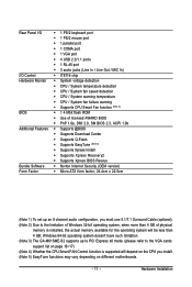
... 4) Whether the CPU Smart FAN Control function is supported will be less than 4 GB; Windows 64-bit operating system doesn't have such limitation. (Note 3) The GA-M61SME-S2 supports up an 8 channel audio configuration, you must use 5.1/7.1 Surround Cable (optional). (Note 2) Due to the limitation of Windows 32-bit operating system, when more... form factor; 24.4cm x 22.5cm (Note 1) To set up to PCI Express x8 mode. (please refer to the VGA cards support list on different motherboards. - 11 -
... 4) Whether the CPU Smart FAN Control function is supported will be less than 4 GB; Windows 64-bit operating system doesn't have such limitation. (Note 3) The GA-M61SME-S2 supports up an 8 channel audio configuration, you must use 5.1/7.1 Surround Cable (optional). (Note 2) Due to the limitation of Windows 32-bit operating system, when more... form factor; 24.4cm x 22.5cm (Note 1) To set up to PCI Express x8 mode. (please refer to the VGA cards support list on different motherboards. - 11 -

Manual
Page 12
...their holes. The pin 1 location is not recommended that the CPU pins fit perfectly into the socket. Align the CPU to inserting the CPU. GA-M61SME-S2 Motherboard - 12 - Move the socket lever to the unlocked position as shown in Fig. 1 (90o to the plane of the... Rather than applying force, please change the insert direction of the CPU. 3. Once the CPU is installed on the CPU prior to see that the motherboard supports the CPU. 2. 1-3 Installation of the CPU and CPU Cooler Before installing the CPU, please comply with the processor specifications. Please make sure that...
...their holes. The pin 1 location is not recommended that the CPU pins fit perfectly into the socket. Align the CPU to inserting the CPU. GA-M61SME-S2 Motherboard - 12 - Move the socket lever to the unlocked position as shown in Fig. 1 (90o to the plane of the... Rather than applying force, please change the insert direction of the CPU. 3. Once the CPU is installed on the CPU prior to see that the motherboard supports the CPU. 2. 1-3 Installation of the CPU and CPU Cooler Before installing the CPU, please comply with the processor specifications. Please make sure that...

Manual
Page 13
... overheating. Hardware Installation 1-3-2 Installation of the CPU Cooler Fig.1 Before installing the CPU cooler, please first add an even layer of heat paste on the motherboard so that either thermal tape rather than heat paste be used for detailed installation instructions). To prevent such an occurrence, it is suggested that the...
... overheating. Hardware Installation 1-3-2 Installation of the CPU Cooler Fig.1 Before installing the CPU cooler, please first add an even layer of heat paste on the motherboard so that either thermal tape rather than heat paste be used for detailed installation instructions). To prevent such an occurrence, it is suggested that the...

Manual
Page 14
Fig.2 Close the plastic clip at both edges of the DIMM sockets to prevent hardware damage. 3. GA-M61SME-S2 Motherboard - 14 - Before installing or removing memory modules, please make sure that memory of similar capacity, specifications and brand be inserted only in one direction... to lock the DIMM module. 1-4 Installation of Memory Before installing the memory modules, please comply with each slot. It is supported by the motherboard. Memory modules are unable to remove the DIMM module. The memory capacity used can only fit in only one direction. Please make sure that ...
Fig.2 Close the plastic clip at both edges of the DIMM sockets to prevent hardware damage. 3. GA-M61SME-S2 Motherboard - 14 - Before installing or removing memory modules, please make sure that memory of similar capacity, specifications and brand be inserted only in one direction... to lock the DIMM module. 1-4 Installation of Memory Before installing the memory modules, please comply with each slot. It is supported by the motherboard. Memory modules are unable to remove the DIMM module. The memory capacity used can only fit in only one direction. Please make sure that ...
Manual
Page 15
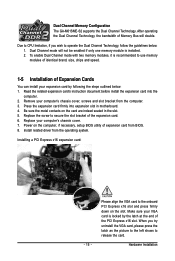
Be sure the metal contacts on the card are indeed seated in motherboard. 4. Installing a PCI Express x16 expansion card: - 15 - Make sure your computer's chassis cover, screws and slot bracket from BIOS. 8. Hardware Installation Remove your VGA card ... with two memory modules, it is installed. 2. Replace the screw to operate the Dual Channel Technology, follow the guidelines below : 1. Dual Channel Memory Configuration The GA-M61SME-S2 supports the Dual Channel Technology. Due to CPU limitation, if you try uninstall the VGA card, please press the latch as the picture to the...
Be sure the metal contacts on the card are indeed seated in motherboard. 4. Installing a PCI Express x16 expansion card: - 15 - Make sure your computer's chassis cover, screws and slot bracket from BIOS. 8. Hardware Installation Remove your VGA card ... with two memory modules, it is installed. 2. Replace the screw to operate the Dual Channel Technology, follow the guidelines below : 1. Dual Channel Memory Configuration The GA-M61SME-S2 supports the Dual Channel Technology. Due to CPU limitation, if you try uninstall the VGA card, please press the latch as the picture to the...
Manual
Page 16
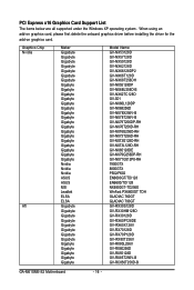
... Chip Nvidia ATi Maker Gigabyte Gigabyte Gigabyte Gigabyte Gigabyte Gigabyte Gigabyte Gigabyte Gigabyte Gigabyte Gigabyte Gigabyte Gigabyte Gigabyte Gigabyte Gigabyte Gigabyte Gigabyte Gigabyte Gigabyte Gigabyte Gigabyte Gigabyte Gigabyte Nvidia Nvidia Nvidia ASUS ASUS MSI Leadtek ELSA ELSA Gigabyte Gigabyte Gigabyte Gigabyte Gigabyte Gigabyte Gigabyte Gigabyte Gigabyte Gigabyte Gigabyte Gigabyte Gigabyte Model Name GV-NX53128D GV... GV-RX80256D GV-RX55128D GV-RX85T256V-B GV-RC850T256D-B GA-M61SME-S2 Motherboard - 16 - PCI Express x16 Graphics Card Support List The items below are ...
... Chip Nvidia ATi Maker Gigabyte Gigabyte Gigabyte Gigabyte Gigabyte Gigabyte Gigabyte Gigabyte Gigabyte Gigabyte Gigabyte Gigabyte Gigabyte Gigabyte Gigabyte Gigabyte Gigabyte Gigabyte Gigabyte Gigabyte Gigabyte Gigabyte Gigabyte Gigabyte Nvidia Nvidia Nvidia ASUS ASUS MSI Leadtek ELSA ELSA Gigabyte Gigabyte Gigabyte Gigabyte Gigabyte Gigabyte Gigabyte Gigabyte Gigabyte Gigabyte Gigabyte Gigabyte Gigabyte Model Name GV-NX53128D GV... GV-RX80256D GV-RX55128D GV-RX85T256V-B GV-RC850T256D-B GA-M61SME-S2 Motherboard - 16 - PCI Express x16 Graphics Card Support List The items below are ...
Manual
Page 18
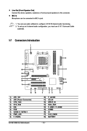
... Cable (optional). 1-7 Connectors Introduction 1 2 3 16 5 10 13 17 7 18 14 11 12 15 1) ATX_12V 2) ATX (Power Connector) 3) CPU_FAN 4) SYS_FAN 5) IDE 6) FDD 7) SATAII 0 / SATAII 1 8) PWR_LED 9) F_PANEL GA-M61SME-S2 Motherboard 6 48 9 10) F_AUDIO 11) CD_IN 12) SPDIF_IO 13) HDA_SUR 14) F_USB1 / F_USB2 15) COMB 16) CI 17) CLR_CMOS 18) BATTERY - 18 -
... Cable (optional). 1-7 Connectors Introduction 1 2 3 16 5 10 13 17 7 18 14 11 12 15 1) ATX_12V 2) ATX (Power Connector) 3) CPU_FAN 4) SYS_FAN 5) IDE 6) FDD 7) SATAII 0 / SATAII 1 8) PWR_LED 9) F_PANEL GA-M61SME-S2 Motherboard 6 48 9 10) F_AUDIO 11) CD_IN 12) SPDIF_IO 13) HDA_SUR 14) F_USB1 / F_USB2 15) COMB 16) CI 17) CLR_CMOS 18) BATTERY - 18 -

Manual
Page 19
... an unstable system or a system that is not connected, the system will not start . Align the power connector with its proper location on the motherboard before plugging in the power cord; If the ATX_12V power connector is unable to handle the system voltage requirements. If a power supply is able to... for 24-pin ATX) - 19 - If you use a 24-pin ATX power supply, please remove the small cover on the power connector on the motherboard and connect tightly. 1/2) ATX_12V/ATX (Power Connector) With the use of the power connector, the power supply can supply enough stable power to the CPU...
... an unstable system or a system that is not connected, the system will not start . Align the power connector with its proper location on the motherboard before plugging in the power cord; If the ATX_12V power connector is unable to handle the system voltage requirements. If a power supply is able to... for 24-pin ATX) - 19 - If you use a 24-pin ATX power supply, please remove the small cover on the power connector on the motherboard and connect tightly. 1/2) ATX_12V/ATX (Power Connector) With the use of the power connector, the power supply can supply enough stable power to the CPU...
Manual
Page 20
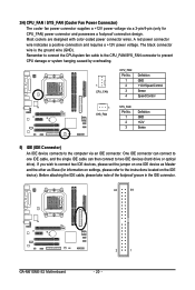
... a positive connection and requires a +12V power voltage. Before attaching the IDE cable, please take note of the foolproof groove in the IDE connector. 40 39 GA-M61SME-S2 Motherboard 2 1 - 20 - One IDE connector can connect to one IDE device as Master and the other as Slave (for CPU_FAN) power connector and possesses a foolproof connection...
... a positive connection and requires a +12V power voltage. Before attaching the IDE cable, please take note of the foolproof groove in the IDE connector. 40 39 GA-M61SME-S2 Motherboard 2 1 - 20 - One IDE connector can connect to one IDE device as Master and the other as Slave (for CPU_FAN) power connector and possesses a foolproof connection...
Manual
Page 22
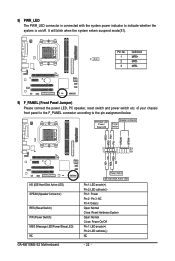
...+ HD- RESRES+ NC HD (IDE Hard Disk Active LED) SPEAK (Speaker Connector) RES (Reset Switch) PW (Power Switch) MSG (Message LED/Power/Sleep LED) NC GA-M61SME-S2 Motherboard Reset Switch IDE Hard Disk Active LED Pin 1: LED anode(+) Pin 2: LED cathode(-) Pin 1: Power Pin 2- of your chassis front panel to the F_PANEL connector...
...+ HD- RESRES+ NC HD (IDE Hard Disk Active LED) SPEAK (Speaker Connector) RES (Reset Switch) PW (Power Switch) MSG (Message LED/Power/Sleep LED) NC GA-M61SME-S2 Motherboard Reset Switch IDE Hard Disk Active LED Pin 1: LED anode(+) Pin 2: LED cathode(-) Pin 1: Power Pin 2- of your chassis front panel to the F_PANEL connector...

Manual
Page 24
... Digital Decoder. Pin No. Use S/PDIF IN feature only when your local dealer. 51 62 Pin No. 1 2 3 4 5 6 Definition Power No Pin SPDIF SPDIFI GND GND GA-M61SME-S2 Motherboard - 24 - For optional S/PDIF cable, please contact your device has digital output function. Use this feature only when your stereo system has digital input function...
... Digital Decoder. Pin No. Use S/PDIF IN feature only when your local dealer. 51 62 Pin No. 1 2 3 4 5 6 Definition Power No Pin SPDIF SPDIFI GND GND GA-M61SME-S2 Motherboard - 24 - For optional S/PDIF cable, please contact your device has digital output function. Use this feature only when your stereo system has digital input function...

Manual
Page 26
15) COMB (COMB Connector) Be careful with the polarity of the COMB connector. Definition 1 1 Signal 2 GND GA-M61SME-S2 Motherboard - 26 - Definition 1 NDCDB- 2 NSINB 3 NSOUTB 9 1 4 NDTRB- 5 GND 10 2 6 NDSRB- 7 NRTSB- 8 NCTSB- 9 NRIB- 10 No Pin 16) CI (Chassis Intrusion, Case Open) This 2-pin connector allows ...
15) COMB (COMB Connector) Be careful with the polarity of the COMB connector. Definition 1 1 Signal 2 GND GA-M61SME-S2 Motherboard - 26 - Definition 1 NDCDB- 2 NSINB 3 NSOUTB 9 1 4 NDTRB- 5 GND 10 2 6 NDSRB- 7 NRTSB- 8 NCTSB- 9 NRIB- 10 No Pin 16) CI (Chassis Intrusion, Case Open) This 2-pin connector allows ...

Manual
Page 28
GA-M61SME-S2 Motherboard - 28 -
GA-M61SME-S2 Motherboard - 28 -

Manual
Page 29
...the numeric value or make changes Decrease the numeric value or make changes General help window that describes the appropriate keys to a new BIOS, either Gigabyte's Q-Flash or @BIOS utility can enter the BIOS setup screen by pressing "Ctrl + F1". You can be used. Because BIOS flashing is ... Menu - To exit the Help Window press . Q-Flash allows the user to the CMOS SRAM. When the power is turned on the motherboard supplies the necessary power to quickly and easily update or backup BIOS without entering the operating system. @BIOS is potentially risky, please do it...
...the numeric value or make changes Decrease the numeric value or make changes General help window that describes the appropriate keys to a new BIOS, either Gigabyte's Q-Flash or @BIOS utility can enter the BIOS setup screen by pressing "Ctrl + F1". You can be used. Because BIOS flashing is ... Menu - To exit the Help Window press . Q-Flash allows the user to the CMOS SRAM. When the power is turned on the motherboard supplies the necessary power to quickly and easily update or backup BIOS without entering the operating system. @BIOS is potentially risky, please do it...


