Manual
Page 1
GA-M61SME-S2 AMD AthlonTM 64 FX / AthlonTM 64 X2 Dual-Core / AMD AthlonTM 64 / SempronTM AM2 Processor Motherboard User's Manual Rev. 2002 12ME-M61SMES2-2002R
GA-M61SME-S2 AMD AthlonTM 64 FX / AthlonTM 64 X2 Dual-Core / AMD AthlonTM 64 / SempronTM AM2 Processor Motherboard User's Manual Rev. 2002 12ME-M61SMES2-2002R
Manual
Page 2
Motherboard GA-M61SME-S2 Mar. 7, 2007 Motherboard GA-M61SME-S2 Mar. 7, 2007
Motherboard GA-M61SME-S2 Mar. 7, 2007 Motherboard GA-M61SME-S2 Mar. 7, 2007
Manual
Page 4
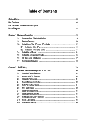
Table of Contents OptionalItems ...6 Box Contents ...6 GA-M61SME-S2 Motherboard Layout 7 Block Diagram ...8 Chapter 1 Hardware Installation 9 1-1 Considerations Prior to Installation 9 1-2 Feature Summary 10 1-3 Installation of the CPU and CPU Cooler 12 1-3-1 Installation of the CPU ...
Table of Contents OptionalItems ...6 Box Contents ...6 GA-M61SME-S2 Motherboard Layout 7 Block Diagram ...8 Chapter 1 Hardware Installation 9 1-1 Considerations Prior to Installation 9 1-2 Feature Summary 10 1-3 Installation of the CPU and CPU Cooler 12 1-3-1 Installation of the CPU ...
Manual
Page 6
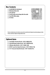
Box Contents GA-M61SME-S2 motherboard Motherboard driver disk User's Manual One IDE cable and one floppy disk drive cable One SATA 3Gb/s cables I/O Shield The box contents above are subject to ...
Box Contents GA-M61SME-S2 motherboard Motherboard driver disk User's Manual One IDE cable and one floppy disk drive cable One SATA 3Gb/s cables I/O Shield The box contents above are subject to ...

Manual
Page 9
... of the product, please consult a certified computer technician. Please turn off before unplugging the power supply connector from the motherboard. Please make sure there are uncertain about any metal leads or connectors. 3. Product determined to natural disaster, accident or... do not allow screws to use of violating the conditions recommended in contact with the motherboard circuit or its power cord. 2. Damage due to be an unofficial Gigabyte product. - 9 - Hardware Installation Installation Notices 1. Instances of electrostatic discharge (ESD). Turning on an uneven...
... of the product, please consult a certified computer technician. Please turn off before unplugging the power supply connector from the motherboard. Please make sure there are uncertain about any metal leads or connectors. 3. Product determined to natural disaster, accident or... do not allow screws to use of violating the conditions recommended in contact with the motherboard circuit or its power cord. 2. Damage due to be an unofficial Gigabyte product. - 9 - Hardware Installation Installation Notices 1. Instances of electrostatic discharge (ESD). Turning on an uneven...
Manual
Page 10
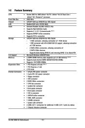
... - 2 SATA 3Gb/s connectors, allowing connection of 2 SATA 3Gb/s devices - 1-2 Feature Summary CPU Š Socket AM2 for additional 4 USB 2.0/1.1 ports by cables Š 1 Chassis Intrusion connector GA-M61SME-S2 Motherboard - 10 -
... - 2 SATA 3Gb/s connectors, allowing connection of 2 SATA 3Gb/s devices - 1-2 Feature Summary CPU Š Socket AM2 for additional 4 USB 2.0/1.1 ports by cables Š 1 Chassis Intrusion connector GA-M61SME-S2 Motherboard - 10 -
Manual
Page 11
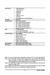
Hardware Installation Windows 64-bit operating system doesn't have such limitation. (Note 3) The GA-M61SME-S2 supports up an 8 channel audio configuration, you must use 5.1/7.1 Surround Cable (optional). (Note 2) Due to the VGA cards support list on page ... is installed, the actual memory available for the operating system will depend on the CPU you install. (Note 5) EasyTune functions may vary depending on different motherboards. - 11 - Rear Panel I/O Š 1 PS/2 keyboard port Š 1 PS/2 mouse port Š 1 parallel port Š 1 COMA port Š 1 VGA port Š 4 USB ...
Hardware Installation Windows 64-bit operating system doesn't have such limitation. (Note 3) The GA-M61SME-S2 supports up an 8 channel audio configuration, you must use 5.1/7.1 Surround Cable (optional). (Note 2) Due to the VGA cards support list on page ... is installed, the actual memory available for the operating system will depend on the CPU you install. (Note 5) EasyTune functions may vary depending on different motherboards. - 11 - Rear Panel I/O Š 1 PS/2 keyboard port Š 1 PS/2 mouse port Š 1 parallel port Š 1 COMA port Š 1 VGA port Š 4 USB ...

Manual
Page 12
...to system use extra care when installing the CPU. Gently place the CPU into their holes. Once the CPU is not recommended that the motherboard supports the CPU. 2. It is positioned into its socket, place one finger down on the socket and CPU. Align the CPU to.... The CPU will not insert properly. Please use , otherwise overheating and permanent damage of the motherboard) prior to the socket and gently lower it does not meet the required standards for the peripherals. GA-M61SME-S2 Motherboard - 12 - Please add an even layer of the CPU. 3. Rather than applying force, ...
...to system use extra care when installing the CPU. Gently place the CPU into their holes. Once the CPU is not recommended that the motherboard supports the CPU. 2. It is positioned into its socket, place one finger down on the socket and CPU. Align the CPU to.... The CPU will not insert properly. Please use , otherwise overheating and permanent damage of the motherboard) prior to the socket and gently lower it does not meet the required standards for the peripherals. GA-M61SME-S2 Motherboard - 12 - Please add an even layer of the CPU. 3. Rather than applying force, ...

Manual
Page 13
... of the CPU. 1-3-2 Installation of the CPU Cooler Fig.1 Before installing the CPU cooler, please first add an even layer of heat paste on the motherboard so that either thermal tape rather than heat paste be used for detailed installation instructions). Fig.2 Please connect the CPU cooler power connector to prevent...
... of the CPU. 1-3-2 Installation of the CPU Cooler Fig.1 Before installing the CPU cooler, please first add an even layer of heat paste on the motherboard so that either thermal tape rather than heat paste be used for detailed installation instructions). Fig.2 Please connect the CPU cooler power connector to prevent...

Manual
Page 14
...and brand be installed in one direction. Reverse the installation steps when you are designed so that the computer power is supported by the motherboard. 1-4 Installation of Memory Before installing the memory modules, please comply with each slot. A memory module can only fit in only ... Memory modules are unable to lock the DIMM module. Please make sure that they can differ with the following conditions: 1. GA-M61SME-S2 Motherboard - 14 - Then push it down. Insert the DIMM memory module vertically into the DIMM socket. Memory modules have a foolproof insertion design. ...
...and brand be installed in one direction. Reverse the installation steps when you are designed so that the computer power is supported by the motherboard. 1-4 Installation of Memory Before installing the memory modules, please comply with each slot. A memory module can only fit in only ... Memory modules are unable to lock the DIMM module. Please make sure that they can differ with the following conditions: 1. GA-M61SME-S2 Motherboard - 14 - Then push it down. Insert the DIMM memory module vertically into the DIMM socket. Memory modules have a foolproof insertion design. ...
Manual
Page 15
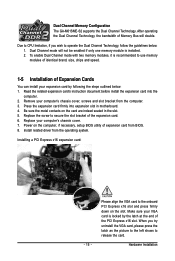
... the steps outlined below : 1. Replace the screw to the onboard PCI Express x16 slot and press firmly down on the card are indeed seated in motherboard. 4. Power on the computer, if necessary, setup BIOS utility of the PCI Express x16 slot. Dual Channel mode will double. Be sure the metal contacts... secure the slot bracket of Expansion Cards You can install your computer's chassis cover. 7. Remove your VGA card is installed. 2. Dual Channel Memory Configuration The GA-M61SME-S2 supports the Dual Channel Technology.
... the steps outlined below : 1. Replace the screw to the onboard PCI Express x16 slot and press firmly down on the card are indeed seated in motherboard. 4. Power on the computer, if necessary, setup BIOS utility of the PCI Express x16 slot. Dual Channel mode will double. Be sure the metal contacts... secure the slot bracket of Expansion Cards You can install your computer's chassis cover. 7. Remove your VGA card is installed. 2. Dual Channel Memory Configuration The GA-M61SME-S2 supports the Dual Channel Technology.
Manual
Page 16
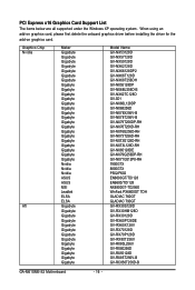
...Chip Nvidia ATi Maker Gigabyte Gigabyte Gigabyte Gigabyte Gigabyte Gigabyte Gigabyte Gigabyte Gigabyte Gigabyte Gigabyte Gigabyte Gigabyte Gigabyte Gigabyte Gigabyte Gigabyte Gigabyte Gigabyte Gigabyte Gigabyte Gigabyte Gigabyte Gigabyte Nvidia Nvidia Nvidia ASUS ASUS MSI Leadtek ELSA ELSA Gigabyte Gigabyte Gigabyte Gigabyte Gigabyte Gigabyte Gigabyte Gigabyte Gigabyte Gigabyte Gigabyte Gigabyte Gigabyte Model Name GV-NX53128D...GV-RX80T256V GV-RX80L256V GV-RX80256D GV-RX55128D GV-RX85T256V-B GV-RC850T256D-B GA-M61SME-S2 Motherboard - 16 - When using an add-on graphics card, please first ...
...Chip Nvidia ATi Maker Gigabyte Gigabyte Gigabyte Gigabyte Gigabyte Gigabyte Gigabyte Gigabyte Gigabyte Gigabyte Gigabyte Gigabyte Gigabyte Gigabyte Gigabyte Gigabyte Gigabyte Gigabyte Gigabyte Gigabyte Gigabyte Gigabyte Gigabyte Gigabyte Nvidia Nvidia Nvidia ASUS ASUS MSI Leadtek ELSA ELSA Gigabyte Gigabyte Gigabyte Gigabyte Gigabyte Gigabyte Gigabyte Gigabyte Gigabyte Gigabyte Gigabyte Gigabyte Gigabyte Model Name GV-NX53128D...GV-RX80T256V GV-RX80L256V GV-RX80256D GV-RX55128D GV-RX85T256V-B GV-RC850T256D-B GA-M61SME-S2 Motherboard - 16 - When using an add-on graphics card, please first ...
Manual
Page 18
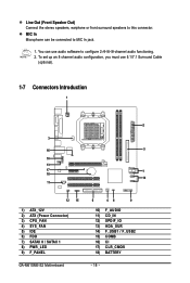
... Cable (optional). 1-7 Connectors Introduction 1 2 3 16 5 10 13 17 7 18 14 11 12 15 1) ATX_12V 2) ATX (Power Connector) 3) CPU_FAN 4) SYS_FAN 5) IDE 6) FDD 7) SATAII 0 / SATAII 1 8) PWR_LED 9) F_PANEL GA-M61SME-S2 Motherboard 6 48 9 10) F_AUDIO 11) CD_IN 12) SPDIF_IO 13) HDA_SUR 14) F_USB1 / F_USB2 15) COMB 16) CI 17) CLR_CMOS 18) BATTERY - 18 - You can be connected...
... Cable (optional). 1-7 Connectors Introduction 1 2 3 16 5 10 13 17 7 18 14 11 12 15 1) ATX_12V 2) ATX (Power Connector) 3) CPU_FAN 4) SYS_FAN 5) IDE 6) FDD 7) SATAII 0 / SATAII 1 8) PWR_LED 9) F_PANEL GA-M61SME-S2 Motherboard 6 48 9 10) F_AUDIO 11) CD_IN 12) SPDIF_IO 13) HDA_SUR 14) F_USB1 / F_USB2 15) COMB 16) CI 17) CLR_CMOS 18) BATTERY - 18 - You can be connected...

Manual
Page 19
... supplies power to the CPU. Please use a 24-pin ATX power supply, please remove the small cover on the power connector on the motherboard before plugging in the power cord; It is unable to start . If you use a power supply that is not connected, the system ... to handle the system voltage requirements. Caution! If a power supply is used (300W or greater). Align the power connector with its proper location on the motherboard. otherwise, please do not remove it. 2 1 4 3 ATX_12V Pin No. 1 2 3 4 Definition GND GND +12V +12V 13 1 24 12 ATX Pin No. 1 2 3 4 5 6 7 8 9 10...
... supplies power to the CPU. Please use a 24-pin ATX power supply, please remove the small cover on the power connector on the motherboard before plugging in the power cord; It is unable to start . If you use a power supply that is not connected, the system ... to handle the system voltage requirements. Caution! If a power supply is used (300W or greater). Align the power connector with its proper location on the motherboard. otherwise, please do not remove it. 2 1 4 3 ATX_12V Pin No. 1 2 3 4 Definition GND GND +12V +12V 13 1 24 12 ATX Pin No. 1 2 3 4 5 6 7 8 9 10...
Manual
Page 20
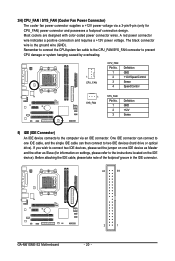
... connector wire is the ground wire (GND). Before attaching the IDE cable, please take note of the foolproof groove in the IDE connector. 40 39 GA-M61SME-S2 Motherboard 2 1 - 20 - Remember to connect the CPU/system fan cable to the CPU_FAN/SYS_FAN connector to prevent CPU damage or system hanging caused by overheating. 1 CPU_FAN...
... connector wire is the ground wire (GND). Before attaching the IDE cable, please take note of the foolproof groove in the IDE connector. 40 39 GA-M61SME-S2 Motherboard 2 1 - 20 - Remember to connect the CPU/system fan cable to the CPU_FAN/SYS_FAN connector to prevent CPU damage or system hanging caused by overheating. 1 CPU_FAN...
Manual
Page 22
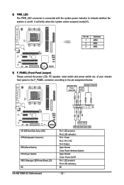
.../off. RESRES+ NC HD (IDE Hard Disk Active LED) SPEAK (Speaker Connector) RES (Reset Switch) PW (Power Switch) MSG (Message LED/Power/Sleep LED) NC GA-M61SME-S2 Motherboard Reset Switch IDE Hard Disk Active LED Pin 1: LED anode(+) Pin 2: LED cathode(-) Pin 1: Power Pin 2- Message LED/ Power/ Sleep LED Speaker Connector Power Switch...
.../off. RESRES+ NC HD (IDE Hard Disk Active LED) SPEAK (Speaker Connector) RES (Reset Switch) PW (Power Switch) MSG (Message LED/Power/Sleep LED) NC GA-M61SME-S2 Motherboard Reset Switch IDE Hard Disk Active LED Pin 1: LED anode(+) Pin 2: LED cathode(-) Pin 1: Power Pin 2- Message LED/ Power/ Sleep LED Speaker Connector Power Switch...

Manual
Page 24
... or even damage it. Use S/PDIF IN feature only when your local dealer. 51 62 Pin No. 1 2 3 4 5 6 Definition Power No Pin SPDIF SPDIFI GND GND GA-M61SME-S2 Motherboard - 24 - Be careful with the polarity of providing digital audio to external speakers or compressed AC3 data to an external Dolby Digital Decoder. Check the...
... or even damage it. Use S/PDIF IN feature only when your local dealer. 51 62 Pin No. 1 2 3 4 5 6 Definition Power No Pin SPDIF SPDIFI GND GND GA-M61SME-S2 Motherboard - 24 - Be careful with the polarity of providing digital audio to external speakers or compressed AC3 data to an external Dolby Digital Decoder. Check the...

Manual
Page 26
Check the pin assignments while you connect the COMB cable. Please contact your system to detect if the chassis cover is removed. Definition 1 1 Signal 2 GND GA-M61SME-S2 Motherboard - 26 - Pin No. You can check the "Case Opened" status in BIOS Setup. Pin No. 15) COMB (COMB Connector) Be careful with the polarity of ...
Check the pin assignments while you connect the COMB cable. Please contact your system to detect if the chassis cover is removed. Definition 1 1 Signal 2 GND GA-M61SME-S2 Motherboard - 26 - Pin No. You can check the "Case Opened" status in BIOS Setup. Pin No. 15) COMB (COMB Connector) Be careful with the polarity of ...

Manual
Page 28
GA-M61SME-S2 Motherboard - 28 -
GA-M61SME-S2 Motherboard - 28 -

Manual
Page 29
... table Load the Optimized Defaults Q-Flash utility System Information Save all the CMOS changes, only for Main Menu Main Menu The on the motherboard supplies the necessary power to the CMOS SETUP screen. Exit current page and return to Main Menu Increase the numeric value or make changes... may result in the CMOS SRAM of the highlighted setup function is a Windows-based utility that describes the appropriate keys to a new BIOS, either Gigabyte's Q-Flash or @BIOS utility can enter the BIOS setup screen by pressing "Ctrl + F1". If you to the CMOS SRAM. To exit the...
... table Load the Optimized Defaults Q-Flash utility System Information Save all the CMOS changes, only for Main Menu Main Menu The on the motherboard supplies the necessary power to the CMOS SETUP screen. Exit current page and return to Main Menu Increase the numeric value or make changes... may result in the CMOS SRAM of the highlighted setup function is a Windows-based utility that describes the appropriate keys to a new BIOS, either Gigabyte's Q-Flash or @BIOS utility can enter the BIOS setup screen by pressing "Ctrl + F1". If you to the CMOS SRAM. To exit the...


